


pucho812
Well-known member
Finally tearing into this thing
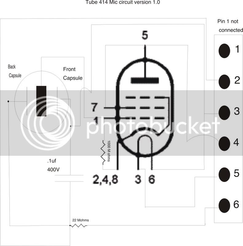
2 resistors in the mic are 1 X 22Mohms and 1X 1000Mohms
the cap in the mic is .1uf 400V
Schematic to follow
2 resistors in the mic are 1 X 22Mohms and 1X 1000Mohms
the cap in the mic is .1uf 400V
Schematic to follow


![Electronics Soldering Iron Kit, [Upgraded] Soldering Iron 110V 90W LCD Digital Portable Soldering Kit 180-480℃(356-896℉), Welding Tool with ON/OFF Switch, Auto-sleep, Thermostatic Design](https://m.media-amazon.com/images/I/41gRDnlyfJS._SL500_.jpg)


 After a third glance. I saw it. Because things were so cramped inside it was hard for me to see what was connected and where. You can see that in the original photos. So I updated the schematic of the mic portion. The cathode goes out to pin2 on the 6 pin XLR

