You are using an out of date browser. It may not display this or other websites correctly.
You should upgrade or use an alternative browser.
You should upgrade or use an alternative browser.
LA-4 Help Thread!
- Thread starter Luny Tune
- Start date


Help Support GroupDIY Audio Forum:
This site may earn a commission from merchant affiliate
links, including eBay, Amazon, and others.
culteousness1
Well-known member
WOW!
Nice frontpanel too. Is it acryl or polished metal?
Cheers,
Carsten
Nice frontpanel too. Is it acryl or polished metal?
Cheers,
Carsten
Hi,
Thanks. I'm really pleased with how it has turned out. I repeat my comment about it being a PITA to wire up, I've built plenty of cramped guitar pedals which held me in good stead. I'll post 'gut shots' when I get chance .
I tend to get all my stuff from mouser, those knobs are: http://uk.mouser.com/Search/ProductDetail.aspx?R=1910CSvirtualkey51200000virtualkey5164-1910CS
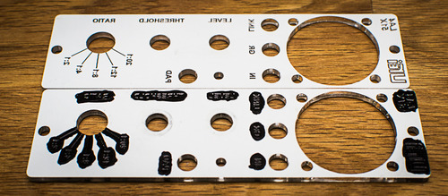
The panel is acrylic backed with mirror finish. The backing gets etched away so that the gap can then be coloured, in this case black marker pen!.
(note: there is a second channel to come)
I'm perpetually blogging my faffings for my own records and for mates to ridicule, feel free to have a look.
I'm going to look over the schematic/layout and try to make sense of the trimmers and what they should be doing, if anyone has any pointers it'd save me a lunchtime!
Thanks,
Ian
Thanks. I'm really pleased with how it has turned out. I repeat my comment about it being a PITA to wire up, I've built plenty of cramped guitar pedals which held me in good stead. I'll post 'gut shots' when I get chance .
I tend to get all my stuff from mouser, those knobs are: http://uk.mouser.com/Search/ProductDetail.aspx?R=1910CSvirtualkey51200000virtualkey5164-1910CS
The panel is acrylic backed with mirror finish. The backing gets etched away so that the gap can then be coloured, in this case black marker pen!.
(note: there is a second channel to come)
I'm perpetually blogging my faffings for my own records and for mates to ridicule, feel free to have a look.
I'm going to look over the schematic/layout and try to make sense of the trimmers and what they should be doing, if anyone has any pointers it'd save me a lunchtime!
Thanks,
Ian
Hi,
Lunchtime has been and gone.
From what I can tell the attached is right.
I do have some questions about the calibration procedure though:
- I'm not sure I can accurately measure the CMR. How is this best done with a basic DMM and/or software oscilloscope?
- The threshold trimmer - I guess this is only really important when you are stereo linking two units (i.e. to get them to behave in a a similar way) is it not possible to do this before anything else - i.e. apply 800mV at input and adjust accordingly?
Thanks,
Ian
Attachments

dissonantstring
Well-known member
irfrench, can you explain with a little more detail about how you make your front panel. i think it really looks nice and maybe a very good option for diy purposes.
as well it is a novel approach to the diy front panel lettering issue many face.
thanks for posting!
best,
grant
as well it is a novel approach to the diy front panel lettering issue many face.
thanks for posting!
best,
grant


$15.98
$16.98
Gikfun Upgraded USB Mini Amplifier Electronic Transparent Stereo Speaker Box Sound Amplifier DIY Kit for Arduino EK1918
Gikfun_Official_Store


![Soldering Iron Kit, 120W LED Digital Advanced Solder Iron Soldering Gun kit, 110V Welding Tools, Smart Temperature Control [356℉-932℉], Extra 5pcs Tips, Auto Sleep, Temp Calibration, Orange](https://m.media-amazon.com/images/I/51sFKu9SdeL._SL500_.jpg)


Hi,
Very happy to share!
I got that panel made by an on-line company in the UK called RazorLab - it was my first use of such a company so a bit nerver wracking. The basic premise is that you create the design in a vector-based art package (in my case I use Inkscape [its free]) upload it to their site and they then use that file to get a laser-cutter to do the work on your chosen panel.
In this case because the 500/51x panel is so small I selected the smallest of the three material size options (small being 180mm x 180mm). You can download a template into which you create your design (use the template to stop accidents such as placing your design outside of the cutting area) which also has handy references for tooling options. For example the machine recognises BLUE as a cutting instruction and RED as an etch instruction.
Its all on their site and explained much better than I can do here!
The reason I wanted to do it like this (other than it looking SWEET!) is that I wanted REALLY accurate holes cut for the pots, switches and in particular the Meter (it needed to be square on the panel and dead-centre due to panel size limitations). There are a number of materials and colours to choose from, and you can colour an etch simply by painting it with acrylic paint, letting that dry and gently scraping off the excess to the the etch, filled.
I placed the order on Thursday and received it on Tuesday - can't grumble with that! The total came to about £25 for the two panels I think, and as there was a bit of spare material I added a couple of trinkets for my two kids (girls) in the form of vanity mirrors with their names engraved on them.
+1 on the panel
+1 grateful, well behaved kids
Win. Win.
I'm toying with the idea of using RazorLab for larger panels such as 1u panels but the main issue (not shared with the 500/51x system) is the weight bearing. I'm definitely going to use them again for 500-51x panels - there are ALWAYS a couple of projects in the pipeline! In any case, I've got another LA4-51x to build and I need to start/finish my second GIX-51x.
'Tis a GREAT time to be a DIY builder.
Regards,
Ian
As, er, promised(?) - some gut shots.
All off-board wiring needed to be done before fitting the PCB into the bracket:
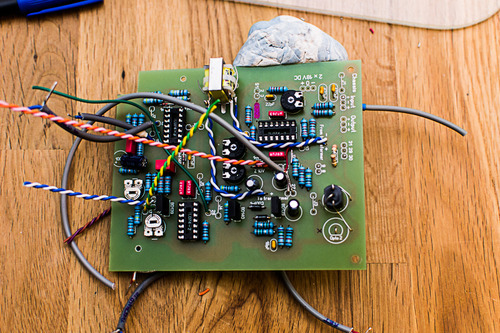
With a bit of luck, some relentless faffing and a pinch of idiocy:
I'm about halfway through the second unit, hopefully my 18pin adapter will arrive soon so I can calibrate these without having my head jammed in a 51x rack.
Thanks again for sharing such an ace project.
Ian
8)
All off-board wiring needed to be done before fitting the PCB into the bracket:
With a bit of luck, some relentless faffing and a pinch of idiocy:
I'm about halfway through the second unit, hopefully my 18pin adapter will arrive soon so I can calibrate these without having my head jammed in a 51x rack.
Thanks again for sharing such an ace project.
Ian
8)
Next time I need an 18pin card slot I'll get it from Volker. Would have done this time had i read the WM thread properly.
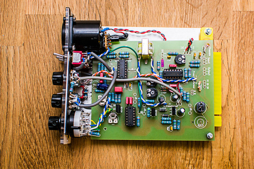
In any case, I got the second channel done:
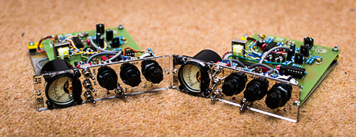
I really want to get these calibrated now. The stereo link is confirmed as working, although they are WAY off in response without calibration.
Am happy with how these turned out. Thanks again for a great project.
Ian.
8)
In any case, I got the second channel done:
I really want to get these calibrated now. The stereo link is confirmed as working, although they are WAY off in response without calibration.
Am happy with how these turned out. Thanks again for a great project.
Ian.
8)
dirtyhanfri
Well-known member
Hi
I'm finishing another unit of this compressor, using NSL32's, 82k for R13, 1k for Ratio Trimmer and 500r for Threshold Trimmer.
But the thing doesn't work fine. The meter reads compression, that looks fine, but nothing changing with the ratio switch, except for 2:1, there I see massive GR, but the same GR for 4, 8, 12 & 20:1.
I didn't heard if the unit passes audio, but as far as I can measure I would say it's not passing. I'm sending a 2v 50hz. signal from my cheap test rig (laptop+ little behringer mixer for controlling levels) and my DMM reads 0V at the output of the transormer, but I can measure signal going into it.
So, 2 main issues, the non working Ratios and the maybe bad output transformer.
I will work first in the ratio issue as I see it harder to solve, but I have no idea in what to look for. I have checked the wiring, the soldering, and it really looks fine.
I'm thinking it could be related to the NSL32's instead Vactrol?
I'll get my working unit today and see If I can find the difference. But if something could give a shot on where to look I'll be pleased.
Thanks
dirtyhanfri
Well-known member
Finally I tried a Vactrol VTL5C4/2 as in my other unit and it works nicely now, the ratios gives me the expected compression. I have audio at the transformer's output and everything looks fine.
I'll build another board for research about the NSL 32 and it's calibration, I've read they're faster and brighter so it could be insteresting. Maybe tweaking Ratio Trimmer and R13?
I've been playing with my unit lately, (I don't mix so much now) and it's quite funny compressor, I really love it on snares and basses, with the voices, when it works, works really good. Just missing a bit more of control on the time response, maybe 2 attack and release positions, but this way makes it a challenge to use it.
Once again, Human Wins ;D
rmaier
Well-known member
Would anyone have mouser numbers, manufacturer numbers or any other information that might help me to find the right package size for the trimmer resistors for this build? I'm having a helluva time finding ones with the right footprint. All of the ones I just received from mouser are the wrong size...
Thanks!
Ralph
Thanks!
Ralph
rmaier
Well-known member
Davo said:I pretty sure I used the Piher ones.... 10mm if I'm not mistaken
http://ca.mouser.com/catalog/catalogcad/646/873.pdf
Cheers
Thanks, Dave. Just installed them today. They fit like a glove.
portix
Active member
Hello,
I try to finish a LA4. I meet some troubles with it:
1) It's very noisy. I've replace the switch S1 by a jumper on the pcb. May it be the cause?
2) 2:1 et 4:1 ratio make a nice compression but for higher values it sound very bad (pumping) What's happend?
3)GR indicator work fine, but the output never go over -20db even while the input is on overload. Normal?
Thanks,
Marc
(Sorry for my poor english)
Edit: After inverting the output transformer the VU seems to be OK.
I try to finish a LA4. I meet some troubles with it:
1) It's very noisy. I've replace the switch S1 by a jumper on the pcb. May it be the cause?
2) 2:1 et 4:1 ratio make a nice compression but for higher values it sound very bad (pumping) What's happend?
3)
Thanks,
Marc
(Sorry for my poor english)
Edit: After inverting the output transformer the VU seems to be OK.

Hey guys,
Just wanted to report on a finished double build.
I had difficult finding VTL5C4/2 (the dual ones), so I went for two VTL5C4.
However after looking at the datasheets it seems these have different resistance curves (the single ones I have have a scale up to 10kOhms, while the double /2 show a scale of 100kOhms), so I have switched R13 (I had tried 150kOm first, this one seems to act as a voltage divider together with the LDR) for a 50KOhm trimmer.
This trimmer seems to end up at around 20-25 kOhms for best calibration results for me.
I think I also changed the GR meter tracking pot (schematic shows 250 kOhm) for a smaller one.
For ratio trim pot I have a 10kOhm pot.
First I tried with NSL32's, but they seemed to to give audible distortion when compressing (it's possible this was due to some other calibration issue though).
This was a pretty long (mostly due to uncertainty and long delivery times) but very interesting build, thanks to all you guys in this thread giving valuable info and insights!.
Attachments

mylesgm
Well-known member
hello irfrench if you are out there... What voltages are your LA4s running at and what's the transformer you used for output?
Similar threads
- Replies
- 0
- Views
- 3K
- Replies
- 38
- Views
- 10K