


- Joined
- Jul 15, 2009
- Messages
- 2,301
D-U67 Build Thread
Let's get those Electron flowing.
All of the info: http://www.groupdiy.com/index.php?topic=49675.0
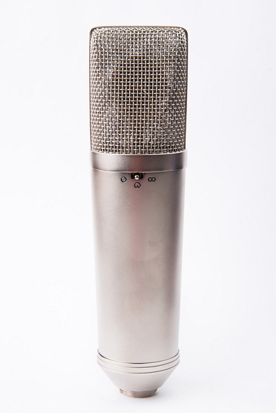
The D-U67 Tube Mic
Mic Assembly Tutorial
https://cdn.groupbuilder.com/groupdiy/u/39511/58d1402a0351f.pdf
PSU Assembly and Tips
https://cdn.groupbuilder.com/groupdiy/u/39511/58d1402a03549.pdf
http:// Check this First: Project Files for The D-U67 Build")
https://cdn.groupbuilder.com/groupdiy/u/39511/58d1402a0356c.zip
The Safety Manual and Considerations.
https://cdn.groupbuilder.com/groupdiy/u/39511/58d1402a0357d.pdf
IMPORTANT:
You Should always have the SHLF Jumper in position in the PSU PCB , this will ensure that your cable shield is tied at both end of the cable and connect to 0V
you Should Also have the 0V star grounded to your case and then from there to you IEC earth ground ,
For More Information on Grounding
https://www.dropbox.com/s/6y121dasm3iw4ba/Sound_System_Interconnection.pdf?dl=0
Best,
Dan,
D-U67 Mic Parts: http://www.mouser.com/ProjectManager/ProjectDetail.aspx?AccessID=83ad963d23
Note: BOM include 56R For R20
D-U67 PSU Parts : http://www.mouser.com/ProjectManager/ProjectDetail.aspx?AccessID=b5c122b4d0
Note: BOM include 560R for R9
OK , here is the briefing
For More Information on Grounding
https://www.dropbox.com/s/6y121dasm3iw4ba/Sound_System_Interconnection.pdf?dl=0
i always have the habit of never float 0V on a PSU i always star ground it to the chassis and then IEC plug ,
about the shield it is imperative at all time that the shield has a path to the chassis as well so it will protect YOU and Your investment. in the mic PCB the shield and 0v are on the same level meaning they are connected togheter and the mouting hole of the pcb are connected to the chassis , this lead to always have the shield protecting you because i ALWAYS star Ground 0V to the power supply case so in all everything always goes to the earth no matter what , So in essence this SHLF is somthing i wanted to implement as a ground lift but it was not done properly and i am glad it turned that way because it is safe this way ,
i guess i am an habit person i always did it like this and never had any problem.
if you have hum problem you can start floating thing arroundb like the 0V from PSU to in respect to Chassis or the shield but it is very something of last resort and i dont recommend it as it is to me potentially unsafe to do so ,
Hope this helps, above is a good read about how to properly ground the equipment togheter,
best,
Dan,
Important Note
Update on PSU Power Specification
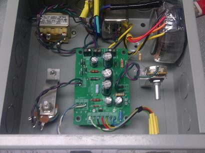
Problem : R2 is getting way too hot
it has been brought to my attention that the PSU Power Supply (R2) Power was out of tolerance and heating passed its
ratings. this has been very isolated case only.
Do Not Use More than 6VA for the 20V transformer
Explanation: the Hammond transformer in the BOM was specified at 300ma 6VA , some DIYER used higher power supply rating cause a bigger Voltage drop in R2 than anticipated supplying more current to it causing the resistor to get too hot and melt the solder on the pcb. those who have used the Specified Hammond transformer can go ahead and only upgrade R2 for the new higher power resistor if needed. Those who have the old hammond transformer should be ok as it cannot outpout enough power to go past 2W specified, only a resistor upgrade is need in this case.
Solution: After Analysis of the power dissipation required on R2 to provide with the Heater Voltage. it has been found that
new higher power R2 Resistor 22ohm 5W to alleviate this as well and it will run cooler. it is also recommended that R2 and the Zener diode shall be lifted a little bit from the PCB to permit better heat disspipation to run even cooler :[/b]
Now Included in the BOM
Here is the 2 suggested part for R2 5Watt as well updated in the BOM
http://ca.mouser.com/Search/ProductDetail.aspx?R=RWHSE09TU025R0FSvirtualkey58440000virtualkey605-RWHSE09TU025R0FS
or
http://ca.mouser.com/Search/ProductDetail.aspx?R=AC05000002209JAC00virtualkey59420000virtualkey594-AC05W22R00J
Many Thanks To TLRT for catching those potential issues.
Best,
Dan,
The only 2 parts that is not (Europe 230V) compatible is the hammond 20VAC and the PSU pilot Lamp wich is 120V everything else is fine except the fuse will need to be 0.1A instead of a 0.2A for north America, you will need a minimun 6VA traffo for the filament side,
alternative part number are discussed in this thread here :
http://www.groupdiy.com/index.php?topic=49675.20
http://www.groupdiy.com/index.php?topic=49675.40
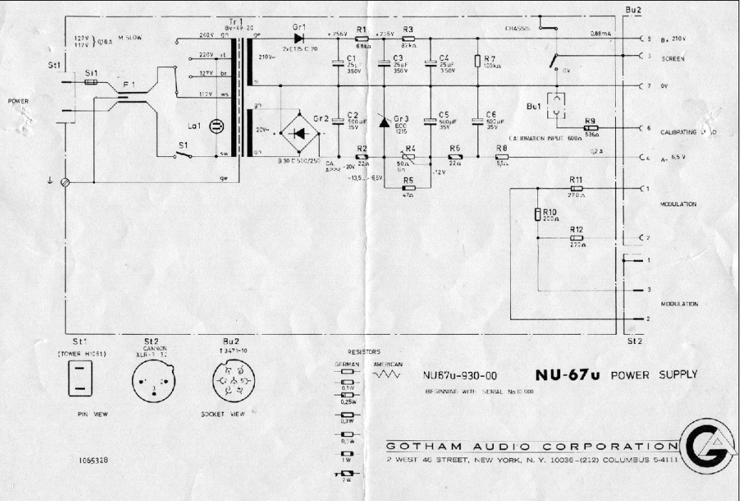
PSU Schematic
https://cdn.groupbuilder.com/groupdiy/u/39511/58d1402a0358d.pdf
Errata Feedback winding polarity http://groupdiy.com/index.php?topic=50021.800 reply # 814
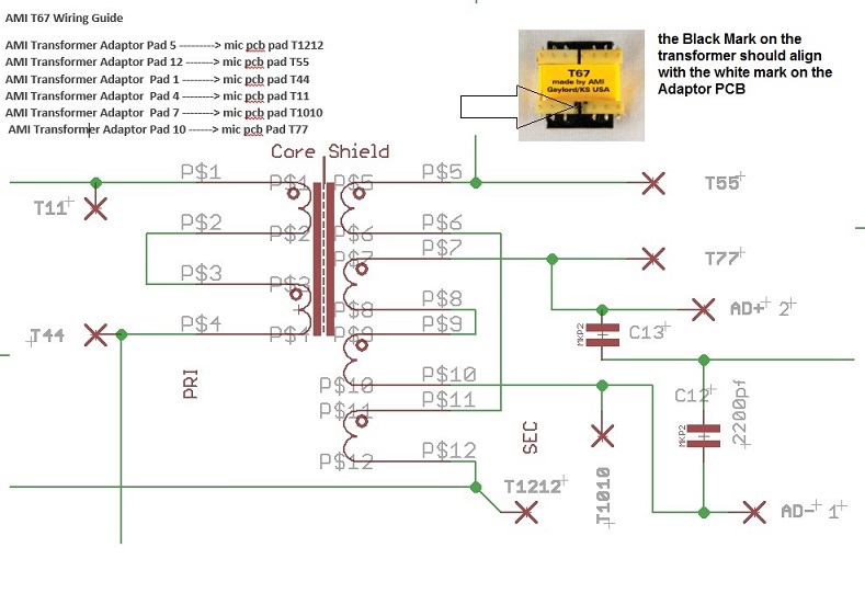
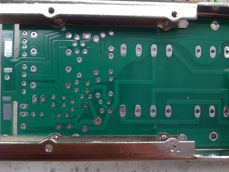
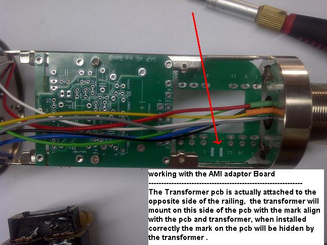
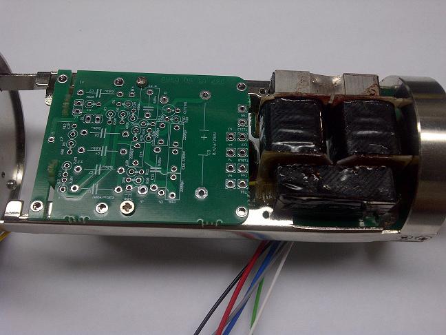
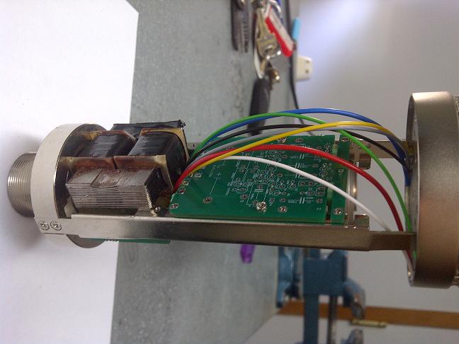
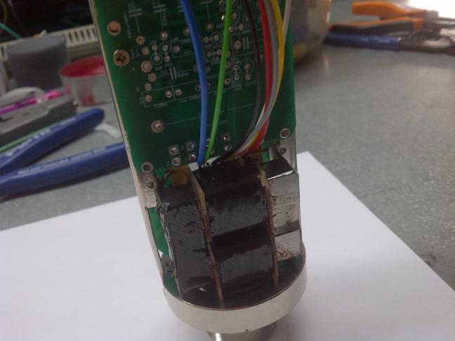
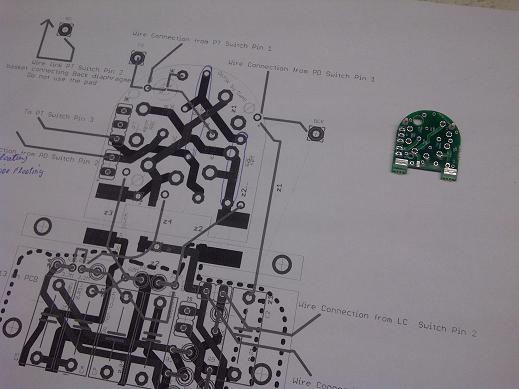
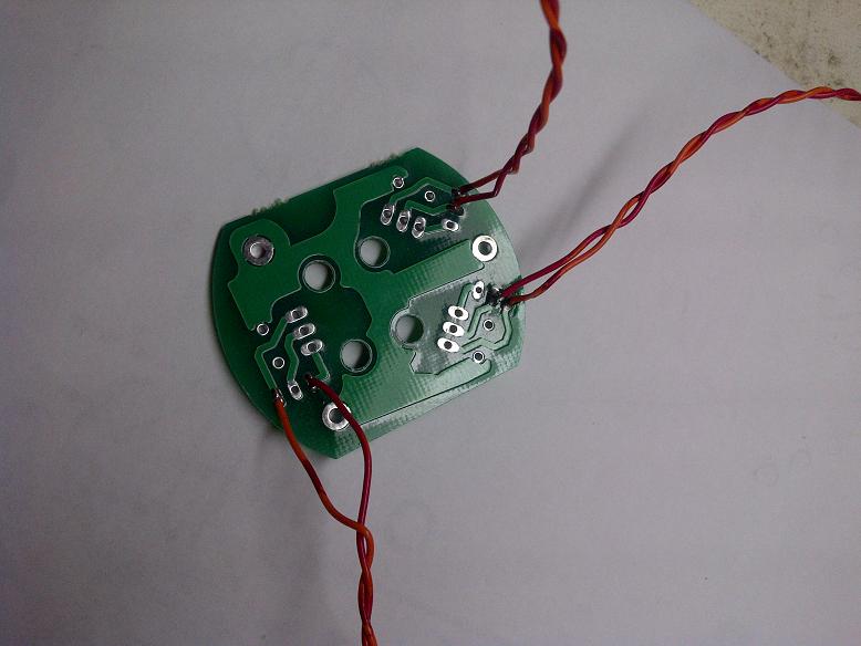
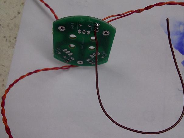
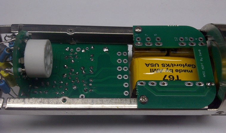
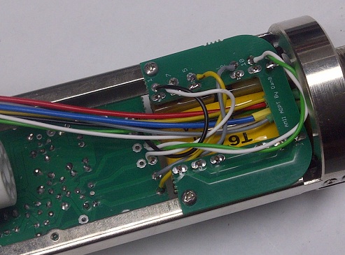
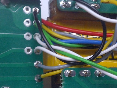
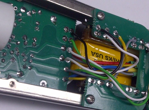
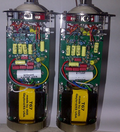
AMI T67 Corrected Wiring to main microphone pcb
From transformer board to mic PCB
Pad 5 -----> mic pcb pad T1212
Pad 12 -------> mic pcb pad T55
Pad 1 --------> mic pcb pad T44
Pad 4 --------> mic pcb pad T11
Pad 7 --------> mic pcb pad T1010
Pad 10 ------> mic pcb Pad T77
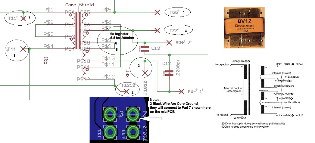
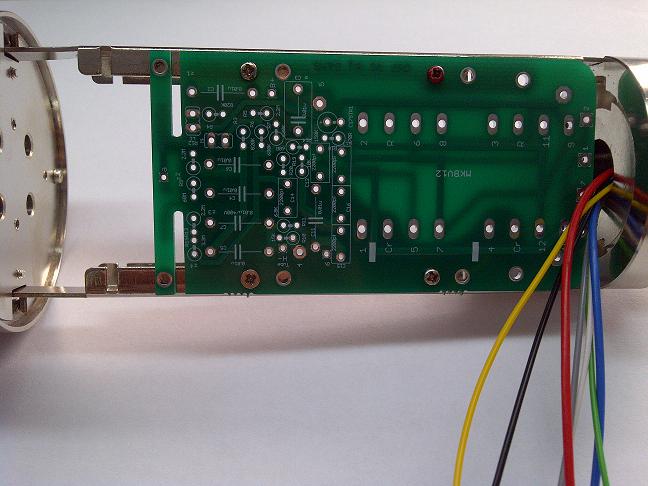
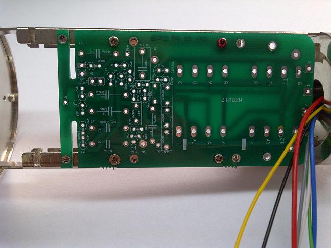
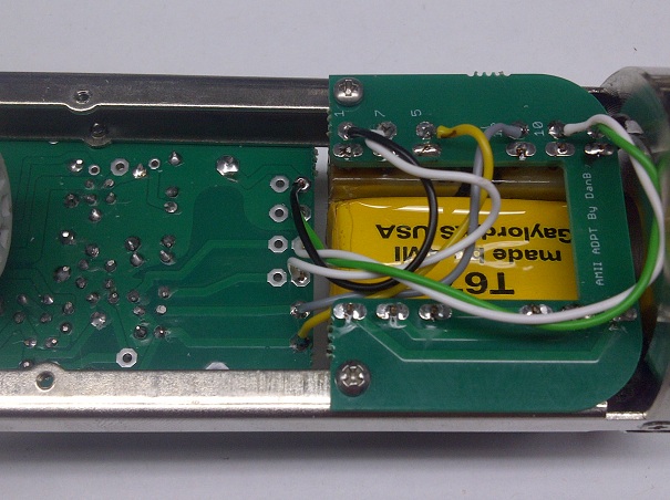
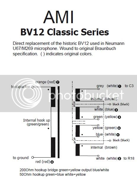
yes i got it this morning , cant wait to start a new build with this traffo. i really like my D-EF47 with the BV8 classic series.
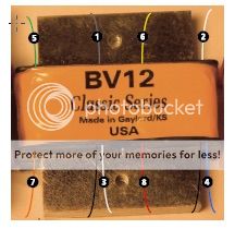
let get this bv12 classic series going
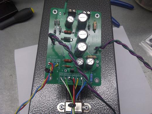
the 2 black wire are actually shiedling of the core, take those 2 wires to a gnd pad onm the pcb,
Also note that the Blue wire (4) is the +audio out and the White (3) is - audio out
https://cdn.groupbuilder.com/groupdiy/u/39511/58d1402a035c5.pdf
best,
Dan.
See here for complete relationship between pad and transfomer on the AMI mic pcb,
http://groupdiy.com/index.php?topic=50021.msg720336#msg720336
BOM Annexe
https://cdn.groupbuilder.com/groupdiy/u/39511/58d1402a035d6.doc
Not inclued in the Mouser Bom are:
Styroflex Capacitor Available Here :http://dl.dropbox.com/u/43869772/U67/Picture%20Tron/orderformDU67.xls
Microphone Body and accessories Available Here :http://www.groupdiy.com/index.php?topic=50015.0
Bellow Basic Setup for Different Version , different folks different strokes 8)
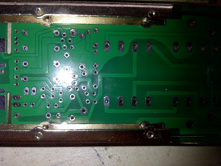
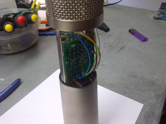
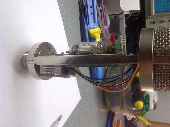
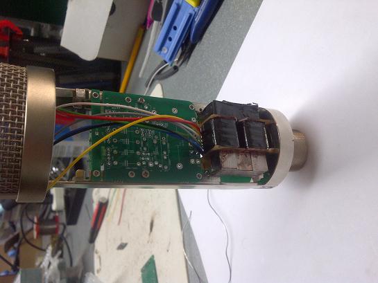
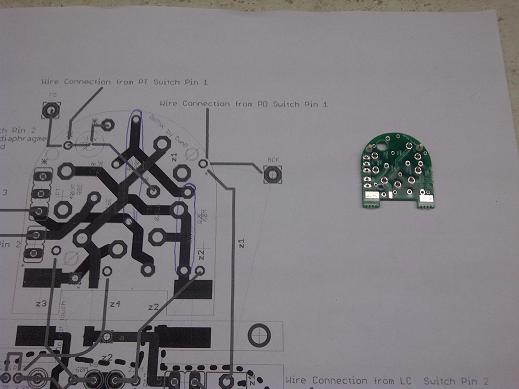
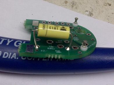
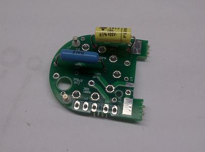
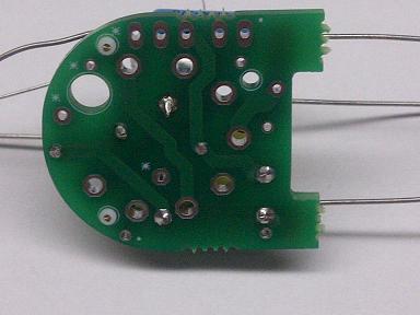
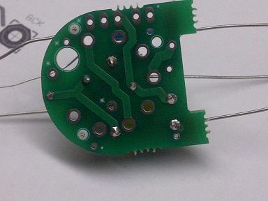
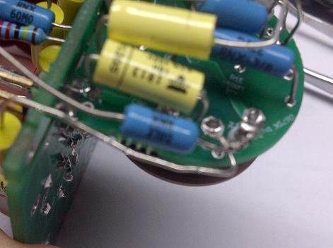
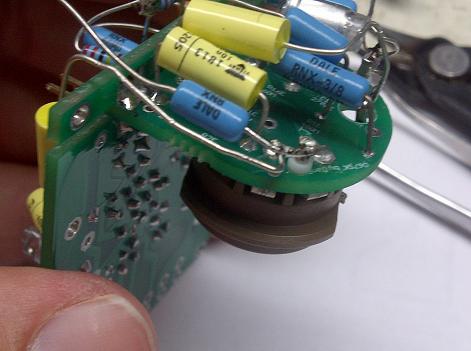
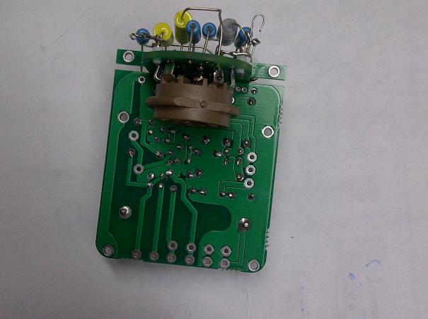
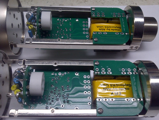
I have been working on validating the last details regarding mouting the AMI boards and last fine tuning regarding the Clearance of the track pad in respect to th railing and position, fit in the mic boady and hole tolerance , I am pleased to annonce that all my concerns on this have been validated ,
here some
AMI or External Board Mounting Hints and clearance railing test,
and Yes this is My favourite Celebration beers the Boddingtons ;D
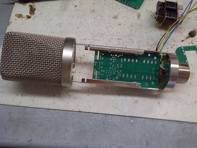
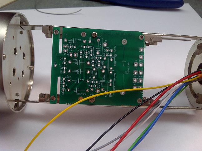
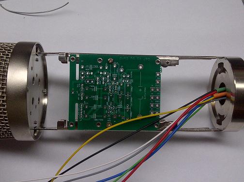
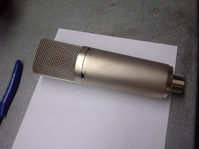
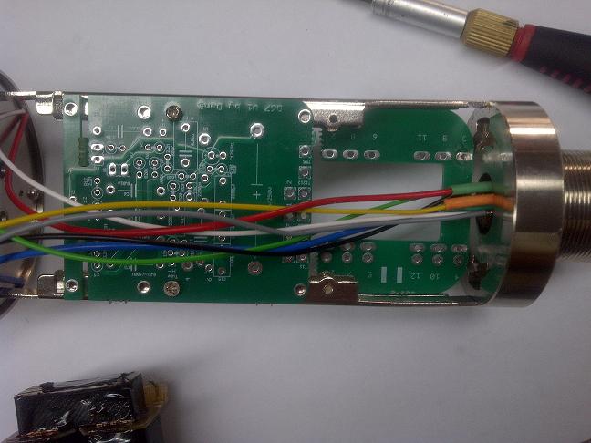
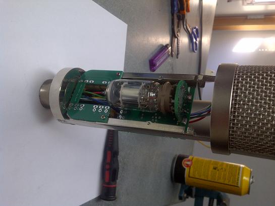
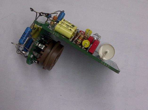
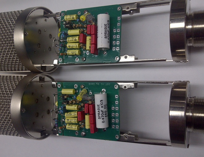
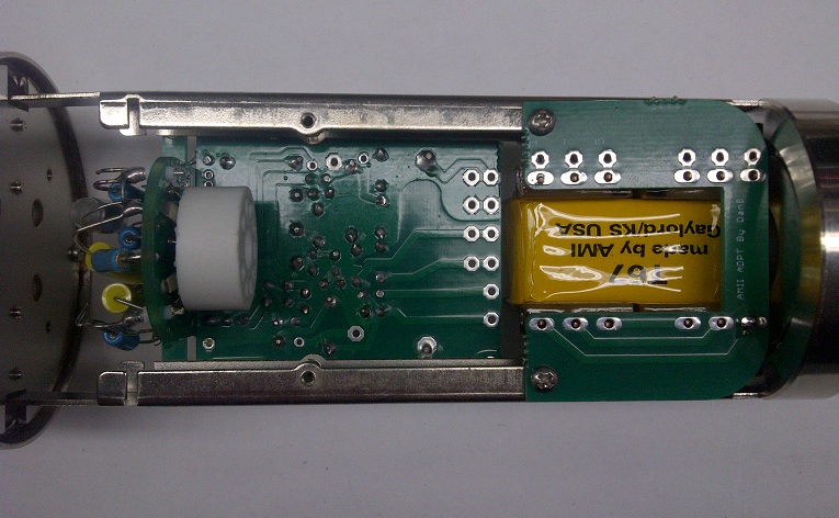
The D-U67 Build
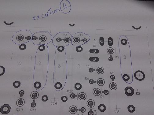
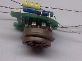
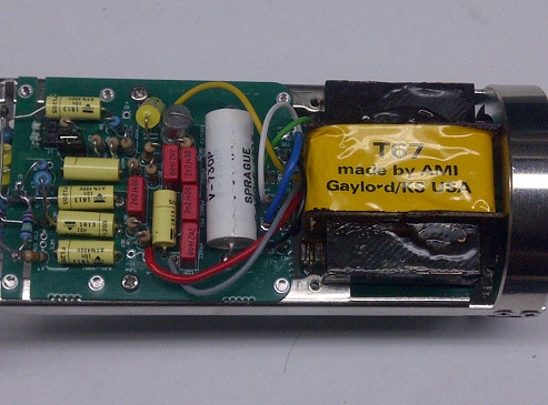
All Of it, 100% original Circuit , No Exception Include Calibration Check Port & Internal LC shift Switch
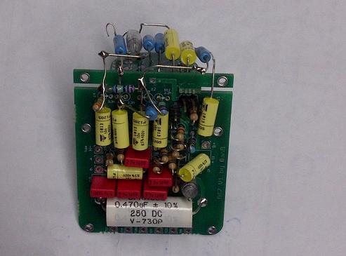
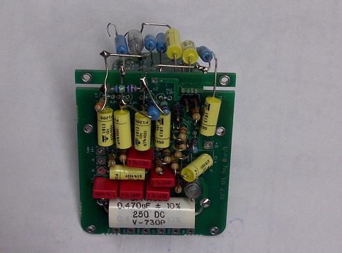
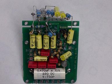
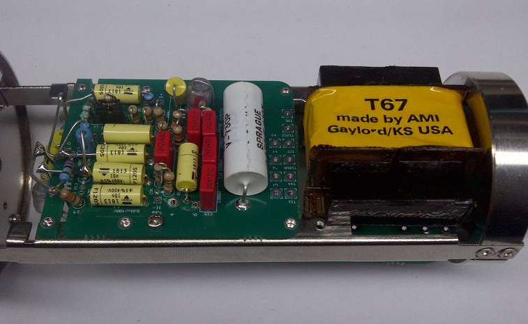
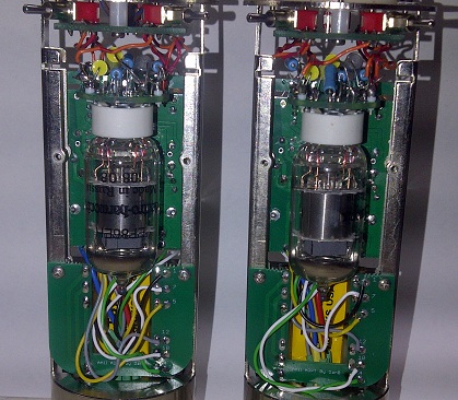
External Transformer Such As Tabfunkenwork AMI T67 PCB shown in Photo Build , Ioaudio BV 12 on the left,
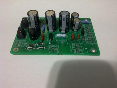
PSU thanks To DanDeurloo
Dan's Case Available here : http://www.collectivecases.com/
or Here: http://www.groupdiy.com/index.php?topic=41963.0

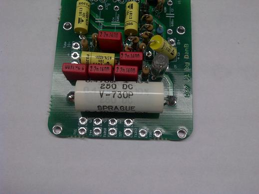
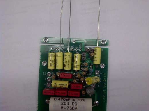
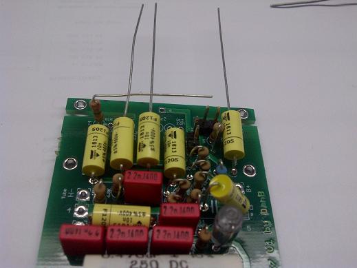
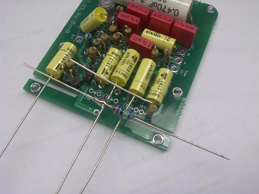
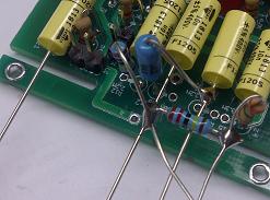
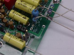
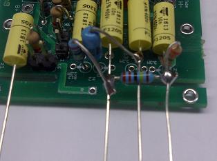
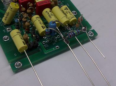
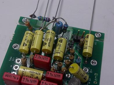
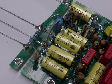
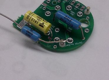
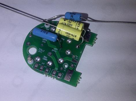
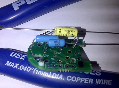
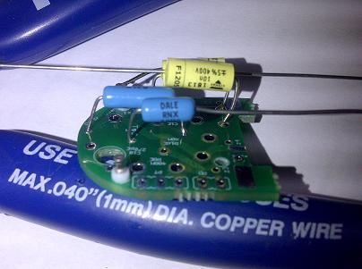
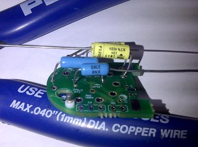
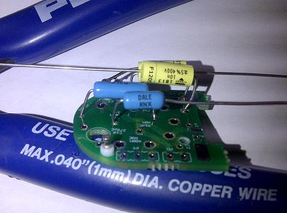
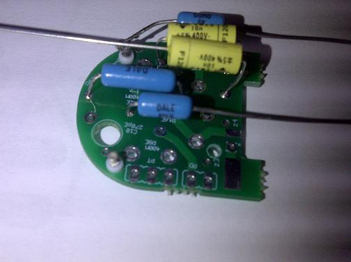
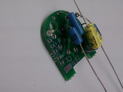
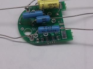
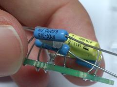
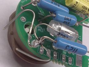
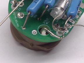
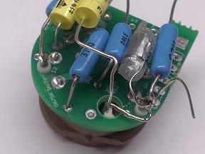
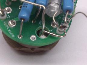
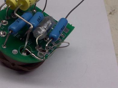
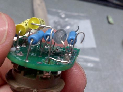
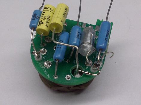
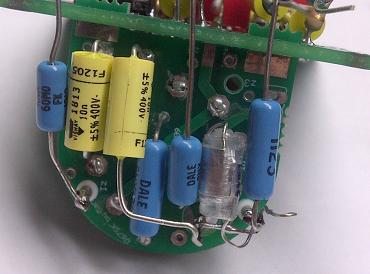
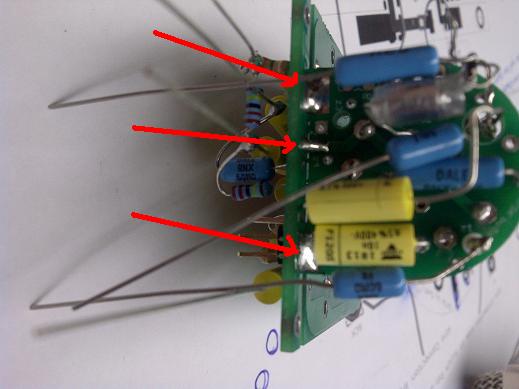
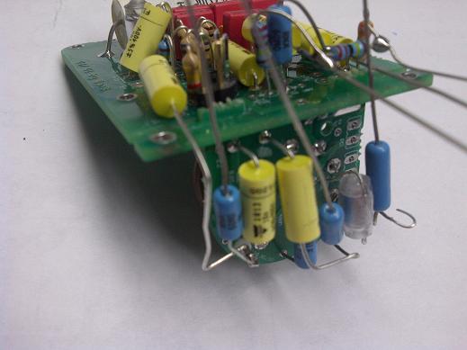
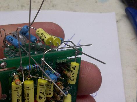
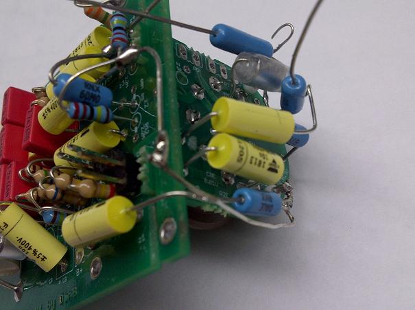
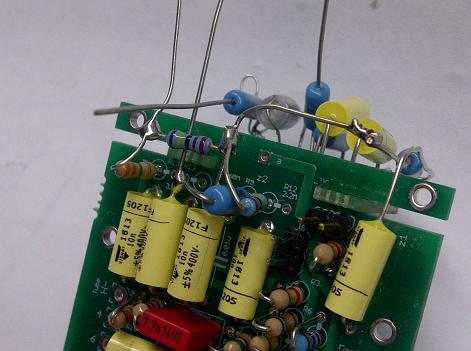
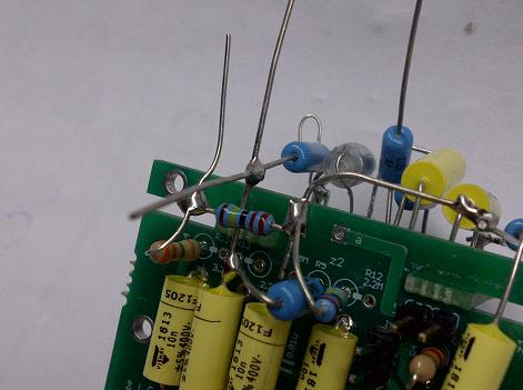
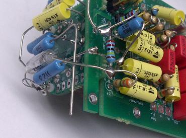
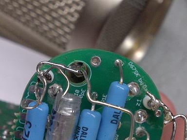
The Build of the HZ floating Bridge uses all the existing resistor and capacitor leads

The D-U67 and the D-M269 Share the same pattern switch , low cut switch, and pad switch wiring. the only difference is for Pattern Swich Pin 1 For A complete switch connection tutorial see here in build Part 2 : http://www.groupdiy.com/index.php?topic=51350.0
AMI T67 Example.

Let's get those Electron flowing.
All of the info: http://www.groupdiy.com/index.php?topic=49675.0
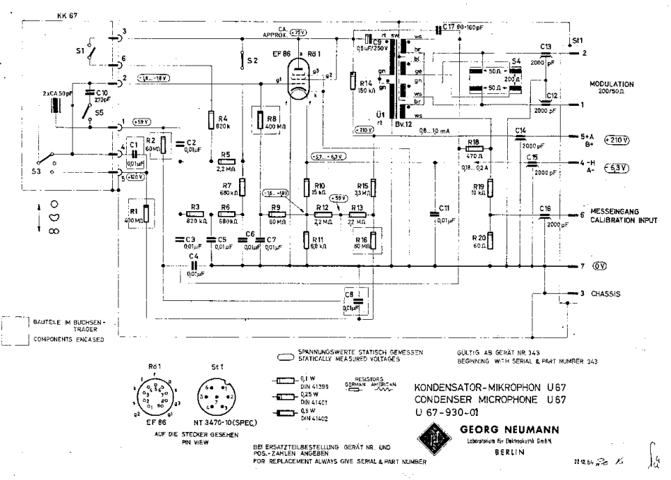
The D-U67 Tube Mic
Mic Assembly Tutorial
https://cdn.groupbuilder.com/groupdiy/u/39511/58d1402a0351f.pdf
PSU Assembly and Tips
https://cdn.groupbuilder.com/groupdiy/u/39511/58d1402a03549.pdf
http:// Check this First: Project Files for The D-U67 Build
https://cdn.groupbuilder.com/groupdiy/u/39511/58d1402a0356c.zip
The Safety Manual and Considerations.
https://cdn.groupbuilder.com/groupdiy/u/39511/58d1402a0357d.pdf
IMPORTANT:
You Should always have the SHLF Jumper in position in the PSU PCB , this will ensure that your cable shield is tied at both end of the cable and connect to 0V
you Should Also have the 0V star grounded to your case and then from there to you IEC earth ground ,
For More Information on Grounding
https://www.dropbox.com/s/6y121dasm3iw4ba/Sound_System_Interconnection.pdf?dl=0
Best,
Dan,
D-U67 Mic Parts: http://www.mouser.com/ProjectManager/ProjectDetail.aspx?AccessID=83ad963d23
Note: BOM include 56R For R20
D-U67 PSU Parts : http://www.mouser.com/ProjectManager/ProjectDetail.aspx?AccessID=b5c122b4d0
Note: BOM include 560R for R9
OK , here is the briefing
For More Information on Grounding
https://www.dropbox.com/s/6y121dasm3iw4ba/Sound_System_Interconnection.pdf?dl=0
i always have the habit of never float 0V on a PSU i always star ground it to the chassis and then IEC plug ,
about the shield it is imperative at all time that the shield has a path to the chassis as well so it will protect YOU and Your investment. in the mic PCB the shield and 0v are on the same level meaning they are connected togheter and the mouting hole of the pcb are connected to the chassis , this lead to always have the shield protecting you because i ALWAYS star Ground 0V to the power supply case so in all everything always goes to the earth no matter what , So in essence this SHLF is somthing i wanted to implement as a ground lift but it was not done properly and i am glad it turned that way because it is safe this way ,
i guess i am an habit person i always did it like this and never had any problem.
if you have hum problem you can start floating thing arroundb like the 0V from PSU to in respect to Chassis or the shield but it is very something of last resort and i dont recommend it as it is to me potentially unsafe to do so ,
Hope this helps, above is a good read about how to properly ground the equipment togheter,
best,
Dan,
Important Note
Update on PSU Power Specification
Problem : R2 is getting way too hot
it has been brought to my attention that the PSU Power Supply (R2) Power was out of tolerance and heating passed its
ratings. this has been very isolated case only.
Do Not Use More than 6VA for the 20V transformer
Explanation: the Hammond transformer in the BOM was specified at 300ma 6VA , some DIYER used higher power supply rating cause a bigger Voltage drop in R2 than anticipated supplying more current to it causing the resistor to get too hot and melt the solder on the pcb. those who have used the Specified Hammond transformer can go ahead and only upgrade R2 for the new higher power resistor if needed. Those who have the old hammond transformer should be ok as it cannot outpout enough power to go past 2W specified, only a resistor upgrade is need in this case.
Solution: After Analysis of the power dissipation required on R2 to provide with the Heater Voltage. it has been found that
new higher power R2 Resistor 22ohm 5W to alleviate this as well and it will run cooler. it is also recommended that R2 and the Zener diode shall be lifted a little bit from the PCB to permit better heat disspipation to run even cooler :[/b]
Now Included in the BOM
Here is the 2 suggested part for R2 5Watt as well updated in the BOM
http://ca.mouser.com/Search/ProductDetail.aspx?R=RWHSE09TU025R0FSvirtualkey58440000virtualkey605-RWHSE09TU025R0FS
or
http://ca.mouser.com/Search/ProductDetail.aspx?R=AC05000002209JAC00virtualkey59420000virtualkey594-AC05W22R00J
Many Thanks To TLRT for catching those potential issues.
Best,
Dan,
The only 2 parts that is not (Europe 230V) compatible is the hammond 20VAC and the PSU pilot Lamp wich is 120V everything else is fine except the fuse will need to be 0.1A instead of a 0.2A for north America, you will need a minimun 6VA traffo for the filament side,
alternative part number are discussed in this thread here :
http://www.groupdiy.com/index.php?topic=49675.20
http://www.groupdiy.com/index.php?topic=49675.40
PSU Schematic
https://cdn.groupbuilder.com/groupdiy/u/39511/58d1402a0358d.pdf
Errata Feedback winding polarity http://groupdiy.com/index.php?topic=50021.800 reply # 814
AMI T67 Corrected Wiring to main microphone pcb
From transformer board to mic PCB
Pad 5 -----> mic pcb pad T1212
Pad 12 -------> mic pcb pad T55
Pad 1 --------> mic pcb pad T44
Pad 4 --------> mic pcb pad T11
Pad 7 --------> mic pcb pad T1010
Pad 10 ------> mic pcb Pad T77
rjuly said:Here is the correspondance on the pcb pad for the U67 Mic pcb
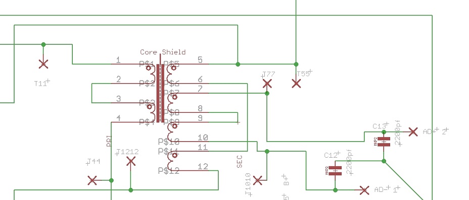
AMI sent me the updated schematic with these details below.
The circuit:
... and the reference image:
Best,
Rich
yes i got it this morning , cant wait to start a new build with this traffo. i really like my D-EF47 with the BV8 classic series.
let get this bv12 classic series going
the 2 black wire are actually shiedling of the core, take those 2 wires to a gnd pad onm the pcb,
Also note that the Blue wire (4) is the +audio out and the White (3) is - audio out
https://cdn.groupbuilder.com/groupdiy/u/39511/58d1402a035c5.pdf
best,
Dan.
See here for complete relationship between pad and transfomer on the AMI mic pcb,
http://groupdiy.com/index.php?topic=50021.msg720336#msg720336
BOM Annexe
https://cdn.groupbuilder.com/groupdiy/u/39511/58d1402a035d6.doc
Not inclued in the Mouser Bom are:
- Switches for Switch board.
- 1X 270pf Styroflex/630V
- 1X FeedBack Cap (80-160pf) styroflex/630V
Styroflex Capacitor Available Here :http://dl.dropbox.com/u/43869772/U67/Picture%20Tron/orderformDU67.xls
Microphone Body and accessories Available Here :http://www.groupdiy.com/index.php?topic=50015.0
Bellow Basic Setup for Different Version , different folks different strokes 8)
I have been working on validating the last details regarding mouting the AMI boards and last fine tuning regarding the Clearance of the track pad in respect to th railing and position, fit in the mic boady and hole tolerance , I am pleased to annonce that all my concerns on this have been validated ,
here some
AMI or External Board Mounting Hints and clearance railing test,
and Yes this is My favourite Celebration beers the Boddingtons ;D
The D-U67 Build
All Of it, 100% original Circuit , No Exception
Include Calibration Check Port & Internal LC shift Switch
External Transformer Such As Tabfunkenwork AMI T67 PCB shown in Photo Build , Ioaudio BV 12 on the left,
PSU thanks To DanDeurloo
Dan's Case Available here : http://www.collectivecases.com/
or Here: http://www.groupdiy.com/index.php?topic=41963.0
The Build of the HZ floating Bridge uses all the existing resistor and capacitor leads
The D-U67 and the D-M269 Share the same pattern switch , low cut switch, and pad switch wiring. the only difference is for Pattern Swich Pin 1 For A complete switch connection tutorial see here in build Part 2 : http://www.groupdiy.com/index.php?topic=51350.0
AMI T67 Example.

