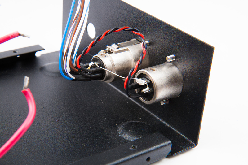
We have lift-off! I moved the backplate connections to another point on the capsule and I replaced C13 with a polypropylene orange drop which I was a little hesitant to do because of urban legend as to the quality of those when used in an audio path but it sounds fine. I also redid the grounds on the cable to the power supply. The thing that puzzled me most was low level noise about 50db down from signal I was getting but had a difficult time pinning down. Now this is a little embarrassing but turns out it was the cooling fans in my Pro Tools PC in a rack about 8 feet away. Now I build these PCs for studios and pride myself in building an exceptionally quiet PC for my customers. It just so happens that this mic is so sensitive it was picking it up exceptionally well. The quietest room in our home is our master bath so that's were I put the mic stringing mic cables through the house and talked my wife into singing a bit, hi pass filter on my Avid Omni did the trick for what little air conditioning noise there was and I'm golden. The top end on this mic is brilliant to say the least and I see no lack of bottom end whatsoever with the stock .56uf output cap.
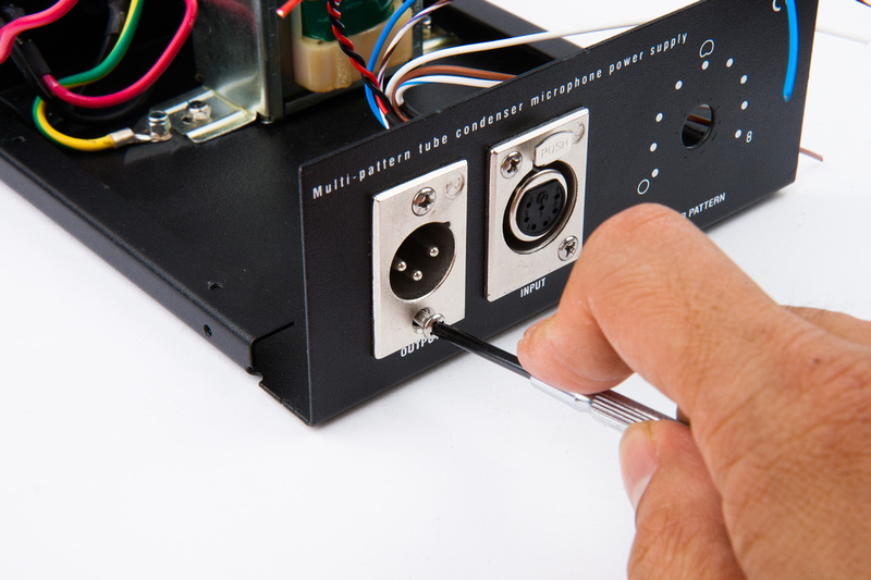
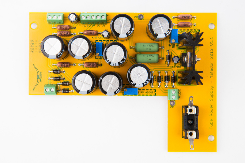
The donor power supply for this was from an Apex 460 that a friend and I modified years ago, the Apex 460 mic itself has a Peluso CEK-89 capsule and a Cinemag CM-2480 output transformer. I will probably redo that mic P2P with the circuit from this guide and have the ability to swap mics as to need until I can build another power supply. I have a Hammond 269AX 250V C.T. 115ma /6.3V 2A power transformer somewhere around here I can use for that. Another project I don't really have time for but that's life. Also need to get a Gotham cable for this mic at some point.
Thanks so much for the guide and the help! 8)


