Discrete OpAmp Test Jig

GroupDIY Audio Forum

Help Support GroupDIY Audio Forum:

This site may earn a commission from merchant affiliate links, including eBay, Amazon, and others.

culteousness1

Well-known member
Joined
Feb 20, 2010
Messages
399
Location
Cologne, Germany
Hi Team,

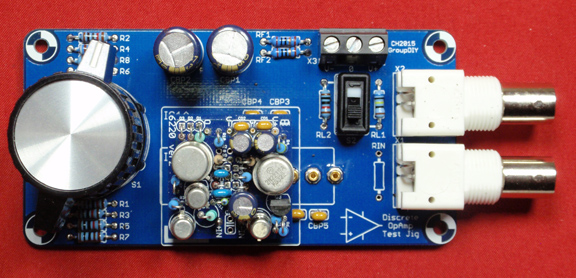
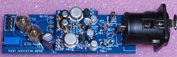
I just wanted to share my DOA Test Jig with you:

doa_testjig1.jpg


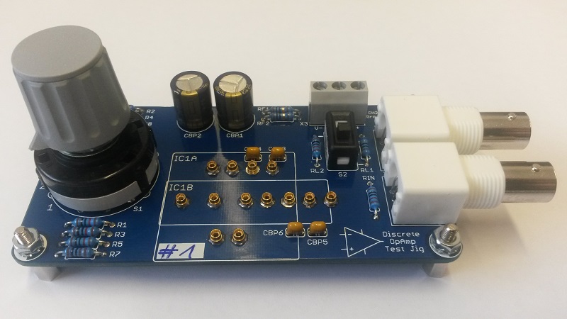
It takes both 2520 and Neumann type DOAs. Two switchable loads are available.
There are four gain settings selectable. Two are set as a inverting amplifier and two
are set to non-inverting.

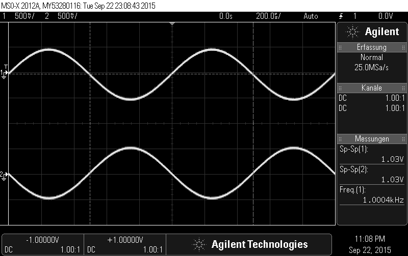
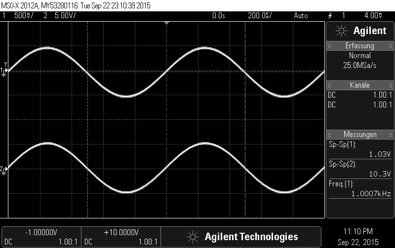
The two pictures below show a screen capture from a measurement. Channel 1 is the
input signal and channel 2 the output of the DOA. The first capture depicts a  inverting
amp with a gain of 0 dB. The second one has 20 dB of gain in non-inverting set-up:

inv_0dB.png

non-inv_20dB.png


The board comes in quite handy when assembling and testing DOAs.
Thanks to Volker for the prototype testing!

Questions and comments are welcome  ;)

Cheers,
Carsten
 
Back in the 70's I used to test purchased IC op amps for my kit company (so I would know they were good before the customer messed with them). 

I used a zero insertion force socket for testing 1,000 op amps at a sitting. I was testing quad op amps so  I ran my signal through all four sections in series. I used inverting topology so I could step up the noise gain with another resistor to ground from the - inputs. So while the signal passed with unity gain, I could test the op amps at 40+ dB of noise gain.  Since 4 stages with 40 dB of noise gain were not very quiet, all that gain would make unusual input noise, or weak open loop gain immediately apparent.

If testing at a single frequency use 10-20kHz so the op amp has to work hard.

FWIW back in the '70s I would only cull out a single digit handfuls of marginal (often working but not as good as the others) from a 1k batch. By the '80s I didn't find enough bad parts to justify 100% testing.

JR
 
JohnRoberts said:
If testing at a single frequency use 10-20kHz so the op amp has to work hard.

I often sweep up to 500 kHz depending on the DOA and the test generator.
Especially for the GAR2520 you can easily see the impact of the input capacitor
at higher frequencies. IIRC at about 240 kHz ;D

Best,
Carsten
 
Love your test jig Carsten !! 8)
NICE JOB!!!
Got an extra PCB??

This would be great for my bench as I am currently using
a 553 on the bench for a test jig.

This is the guy I am using for production run burn ins
It will burn in 20 at a time and you can listen to them
in stereo pairs with out removing them from the burn in
rig.  This works well but is impractical for the bench.

GARY


Attachments

  • Test jig.gif
    Test jig.gif
    144.7 KB · Views: 363
Yes, I do have some spare PCBs.

But as there is no such thing as an error-free PCB, this board contains a small issue too  :mad:
It needs a little bending and some patience to fit the rotary switch. Obviously the EAGLE
stock library has two pins misaligned and I didn't double-check  ::)

But as you can see from the picture above the switch gets in.

If there is more interest, I will start a BM thread as well.

Cheers,
Carsten
 
As Udo will soon receive his board, I wanted to show everyone how to prepare the rotary switch before soldering  ;D

This fix only applies to boards of Revision 1.0 from the initial batch.

The fix only applies to the terminals A and C of S1 (see red circles):
switch_fix1.jpg


Then use a flat plier and gently bend the two terminal until they almost align with the pins 3 and 10 (see orange line):
switch_fix2.jpg


Afterwards you can try to push the switch in with a little force until it sits flat on the PCB. Please be as gentle and patient as possible.

Cheers,
Carsten

[EDIT: Pin in description was wrong. ]
[EDIT: Added Revision disclaimer.]
 
Hello,


received the pcb this morning.Went together very fast and easy,the bending of the Lorlin pins works well.
A great little helper,massive thanks Carsten (for the goodies as well ;) ).
It´s already in use now,get them guys,they´re hot!


Best,


Udo.


P.S.:Sorry for the blurry pic,have low light here and a very cheap camera.
 

Attachments

  • +20dB non-inv.JPG
    +20dB non-inv.JPG
    158.3 KB · Views: 261
Oh,I forgot to mention that I used two 1k2 resistors for RL1 because it's a standard value.One is just soldered to the bottom of the pcb.


Udo.
 
For now no capacitive loading. But I am sure the creative builder will be able to fit a capacitor instead of the second load resistor.

Or I would suggest to install sockets in the load resistor terminals and test with any desired load  :eek:

Cheers,
Carsten
 
Carsten

This is a gar6220.  This is an SPA-62 built to a 2520 format.

See:  http://groupdiy.com/index.php?topic=45733.msg573052#msg573052
for details.

I'm using this guy as a balanced receiver in my Sphere Project.

gar6220recv72.jpg


I will mount your DOA jig on a small piece of OAK with standoffs to give it
an old time flavor! ;)

GARY
 
I got my finished finally. I tried to use as many left over parts as possible. Some of the Vishay resistors I used were a little too big to fit side by side so I had to kind of stack them on each other. Now I need a sweet knob and a power supply. Gary, I like your idea of mounting it on some wood. I hope you don't mind if I do the same for mine.

Thanks!

Paul
 

Attachments

  • DOA Test.jpg
    DOA Test.jpg
    1.6 MB · Views: 121
Just finished building my board and realized that you have omitted the 7th pin that are on vintage 2520´s.
Its not possible to drill a hole either where this pin is since there is a track running beneath it.
Do you know if there are sockets with more spacing above the board level?
I know most 2520 types these days only use 6 pins, but i realy dont want to snap of the 7th pin on any of my vintage opamps.

 
Maybe you can reflow the DOA sockets and pull them a little bit out of the PCB to gain some height.
Or drill a new hole and cut some traces and use some wire to replace them afterwards...

Hope this helps,
Carsten
 

Latest posts

Back
Top