Laz EQN1084 eq - journey

GroupDIY Audio Forum

Help Support GroupDIY Audio Forum:

This site may earn a commission from merchant affiliate links, including eBay, Amazon, and others.
Calibration RV4 - Gain Matching EQ in/bypass

dmp said:
This is my understanding:
RV4 sets the level of the EQ. It's purpose is to match the signal level to unity.
So run a signal through the EQ in bypass and observe the level, then engage the EQ and match the level using the trimpot.

[list type=decimal]
[*]I inserted the EQN into my DAW system
[*]With EQ off, I fed the EQN a sine wave and observed the levels showing on my DAW
[*]I reseted all my EQN settings so that it is zero
[*]I turned the EQ on and compared the levels showing on my DAW. If it's higher or lower, I adjusted RV4 till it matched the levels shown when EQ was Off. My levels were O.K. so I did not have to adjust RV4
[/list]
 
"The James Fix"
------------------------------------------------------------------

Apparently there is an issue with this build as outlined by jrowell:
.....................................................................................

The symptom is LF response shelved below about 500 Hz, -1.8dB down, or so, with EQ in and all bands set to off.

If you are doing just mid or top EQ, this is a problem.

If the LF band is set to off, the response droops below 500Hz.

Since I am a vintage N*v-e service technician, I knew the issue would be in the off paths of the LF freq switch.

The offs go to one side of C29, a 10nF. The other end of C29 feeds the BA205 cap buss.

The pot wiper goes to one end of R10, a 12K. The other end of the 12K goes to C30 and to the LO/HI amp input.

The pot wiper is normally permanently connected to the off positions. It is not here.

The offs end of C29 and the wiper end of R10 are also normally connected together. Again, not here. This is pin L on an original BA205 board diagram.

Basically we have two pin L points. They need to be connected.

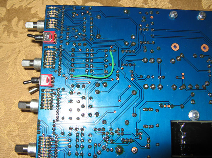
All this can be resolved by connecting the offs end of C29, (side nearest the switch) and the wiper end of R10, (the end closest to the inductor) together with a jumper wire.

Boom, no droop in LF with EQ in and LF set to off.

LF EQ at full cut or boost stays basically identical. Curve is maybe a tad more relaxed.

They actually are a bit flatter than an original, with this corrected.

\\\\\\\\\\\\\\\\\\\\\\\\\\\\\\\\\\\\\\\\\\\\\\\\\\\\\\\\\\\\\\\\\\\\\\\\\\\\\\\\\

I decided to implement this fix:

It wasn't that hard to do, but it was just a pain to go out of my way and pull things apart and put back together again. Have not tested yet whether the fix improved anything but will do so in the future.

1084-fix.jpg
 
Does anyone know the final build cost, budgeting, and it's taking me forever to figure all these kits out!!  :eek:

thanx for your help ;)
 
So Far:
£145 for LAZ kit (the most complete ones since the pins are a PITA to find, and it includes the heatsink)
£157.55 for the GrayHill switches (3x6 pole 1x12 pole), inductors, input transformer from audio maintenance (cheapest around for grayhill atm)
$32 plus shipping and duty to the UK (usually £20) for the EA1166 O/p transformer.

I have a lot of components as I usually buy resistors in big bags (as sold in farnell and rapid) and caps in bags of 10, but still, will have to buy a lot.
Currently, also have:

£66 farnell shopping list for vishay and some other components (Vishay PR6, trimmers, small inductors/chokes)
£30 mouser for components
£35 digikey for the TDK lambda

This is for 1 unit.

Hope it helps
 
Hey,

i'm really interested in building a pair of these badboys. Will there be another batch or is someone willing to sell?

Thanks guys!
 
I have four I've used with 24v but I recently bought the components for the dc-dc convertor so they can run in either, by changing the jumper under the TDK. Not enough room under there to solder in a header though. Anyone come up with a way to do this? I don't want to solder/remove a wire jumper to change from 500 to 51x or back
 
Back
Top