


Since there is sufficient amount of RackNeve kits floating around, I decided to open this official support thread. All build questions will be answered here.
Meanwhile, here're some useful links that will get the builder started:
Standalone units:
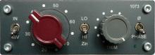
RackNeve 1073-type preamp and EQ building guide.
4-channel frame modules:
Our 4-channel frame system explained.
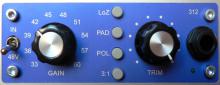
 1290 type mic preamp building guide.
 Passive 1073-type EQ building guide.
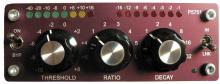
 1176-type compressor building guide.
 PYE-type compressor building guide.
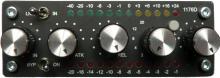
 312-type mic preamp building guide.
Universal PSU building guide.
Meanwhile, here're some useful links that will get the builder started:
Standalone units:
RackNeve 1073-type preamp and EQ building guide.
4-channel frame modules:
Our 4-channel frame system explained.
Universal PSU building guide.


![Soldering Iron Kit, 120W LED Digital Advanced Solder Iron Soldering Gun kit, 110V Welding Tools, Smart Temperature Control [356℉-932℉], Extra 5pcs Tips, Auto Sleep, Temp Calibration, Orange](https://m.media-amazon.com/images/I/51sFKu9SdeL._SL500_.jpg)


