rainton
Well-known member
UPDATE:
GROUP BUY IS CLOSED NOW
I pasted the info here in this first post, so you don't have to search for it
Here's what will be included in this authentic re-creation of a UA 176 chassis kit:
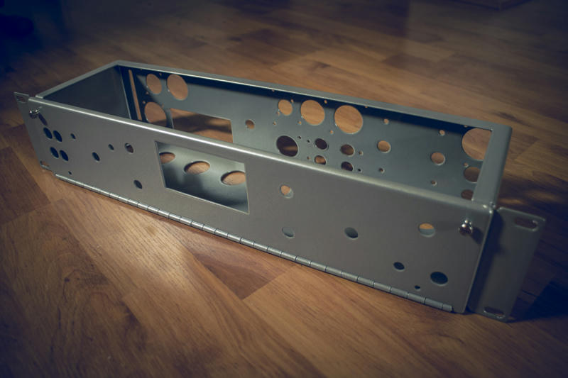
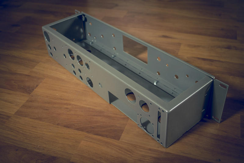
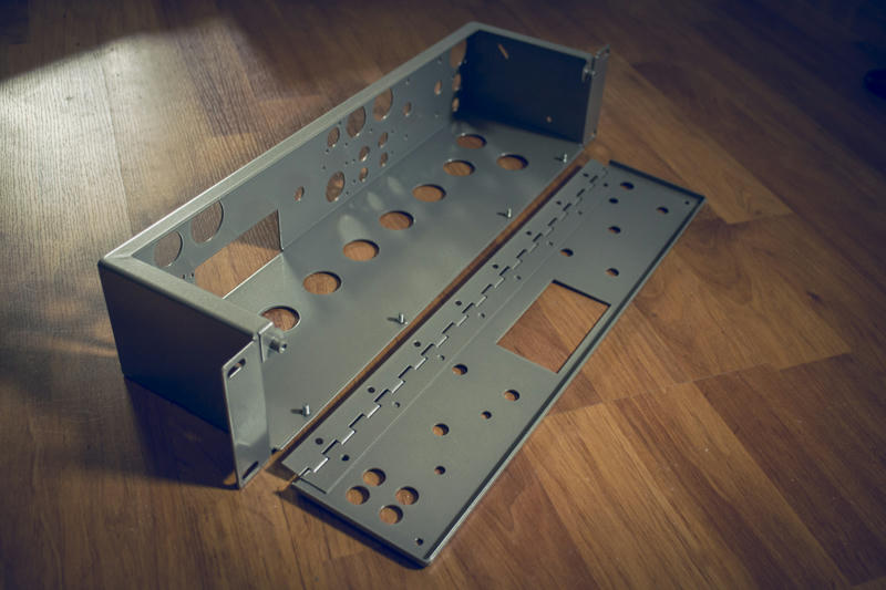
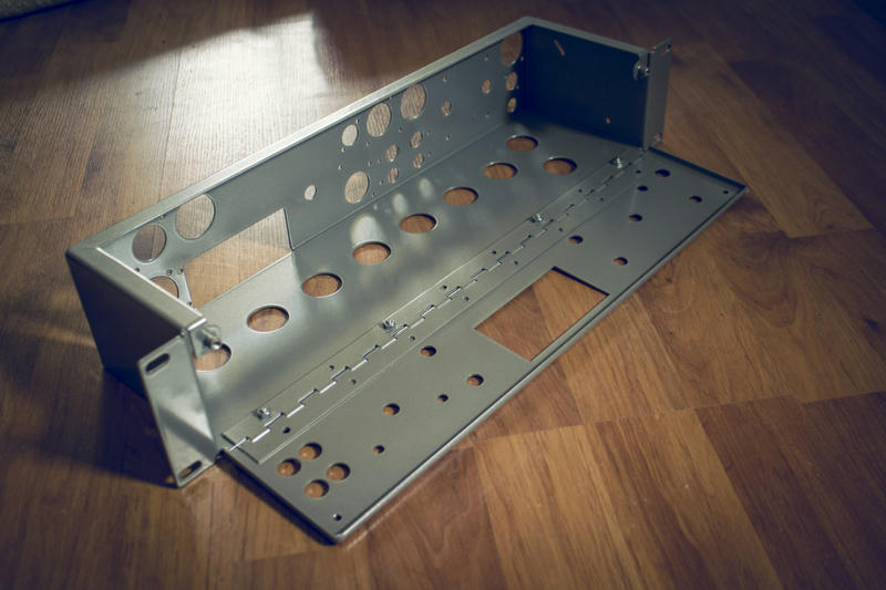
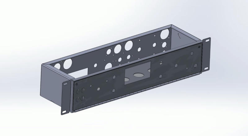
- main chassis, bent, welded, smoothed and powder coated grey
- first front panel - also folded edges, welded smoothed and powder coated grey
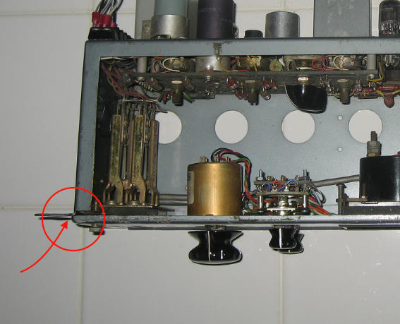
- custom made hinge manufactured following original specs, powder coated and welded to the first front panel
- second front panel to go on top of the first one: this will be the black panel with white silk-screening
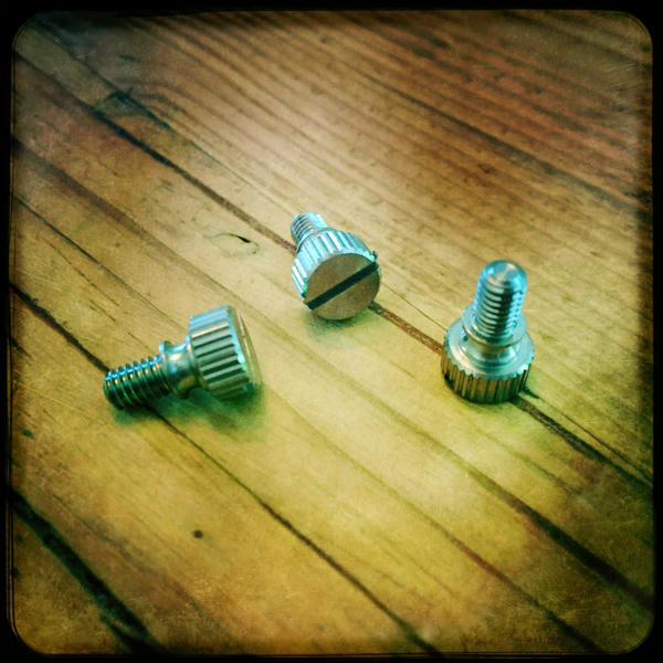
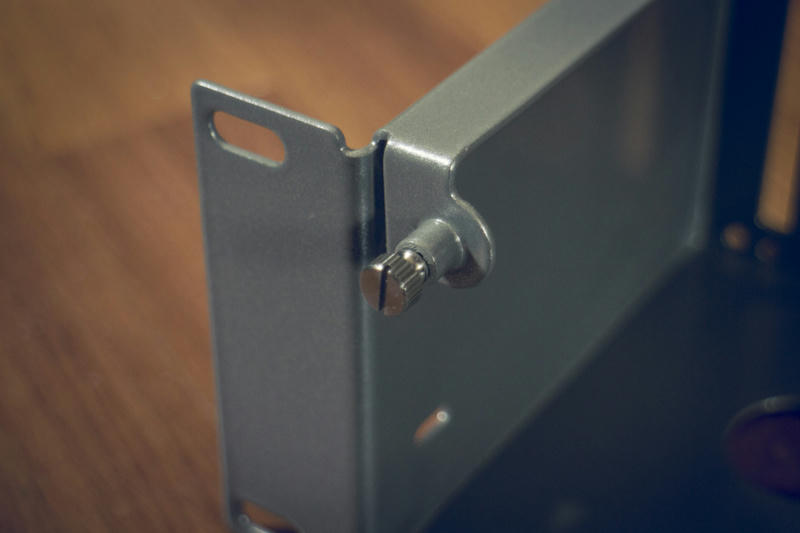
- custom made stainless steel thumb screws designed for original looks
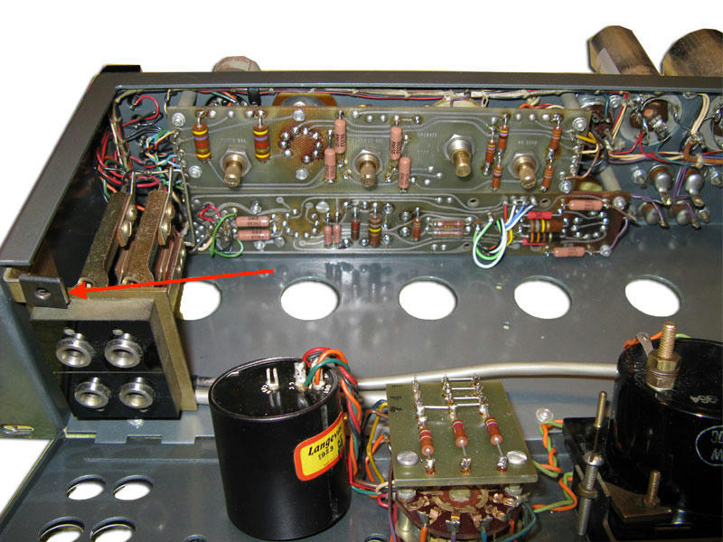
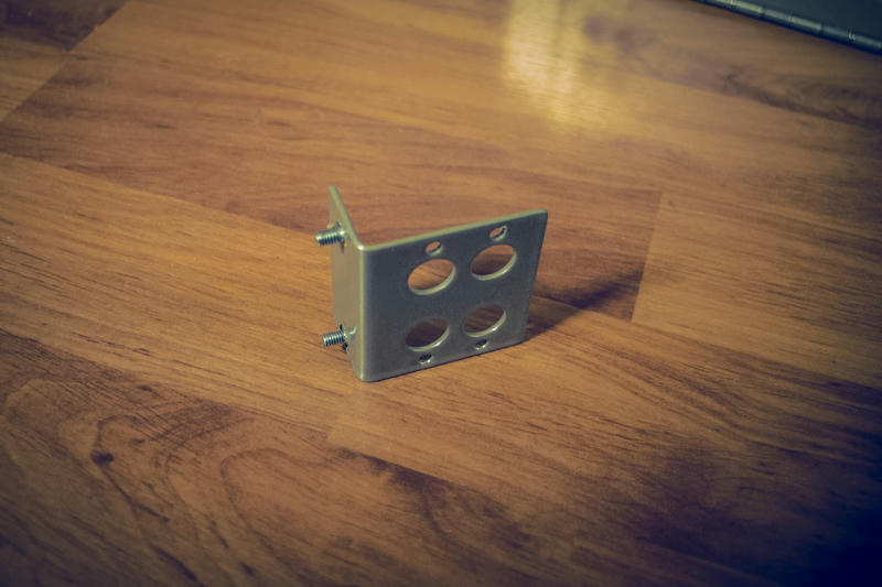
- mounting bracket for input/output jacks on the front
- mounting bracket for optional metering switch inside
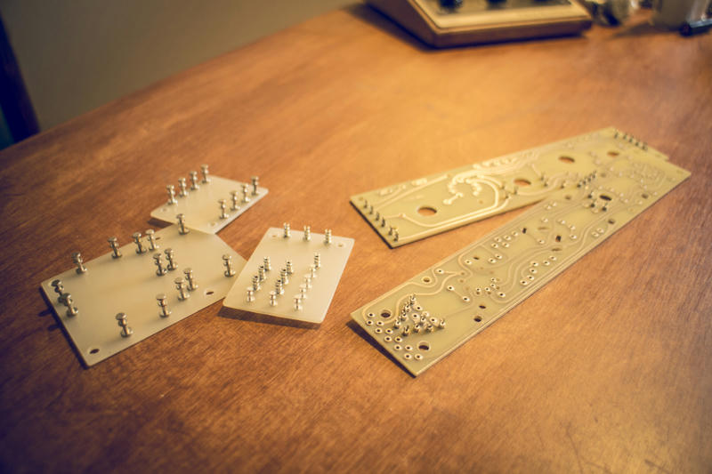
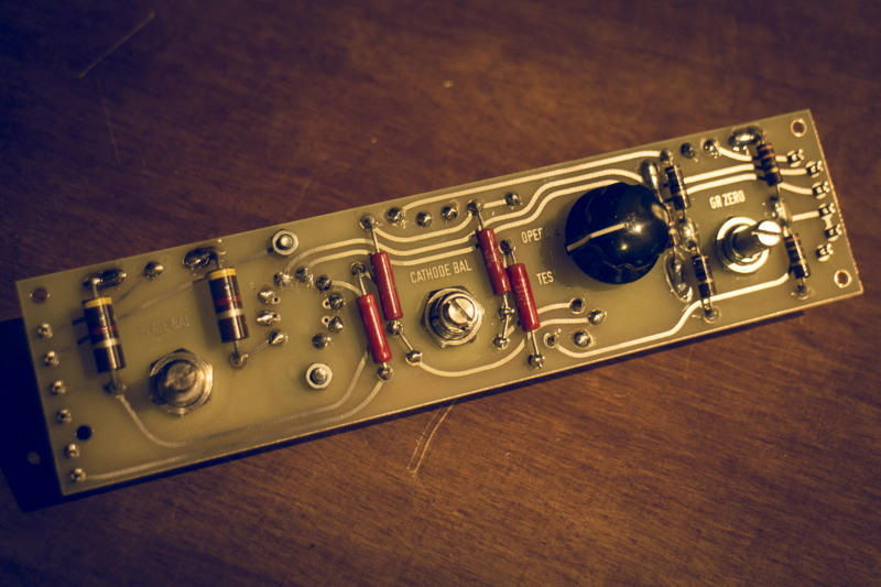
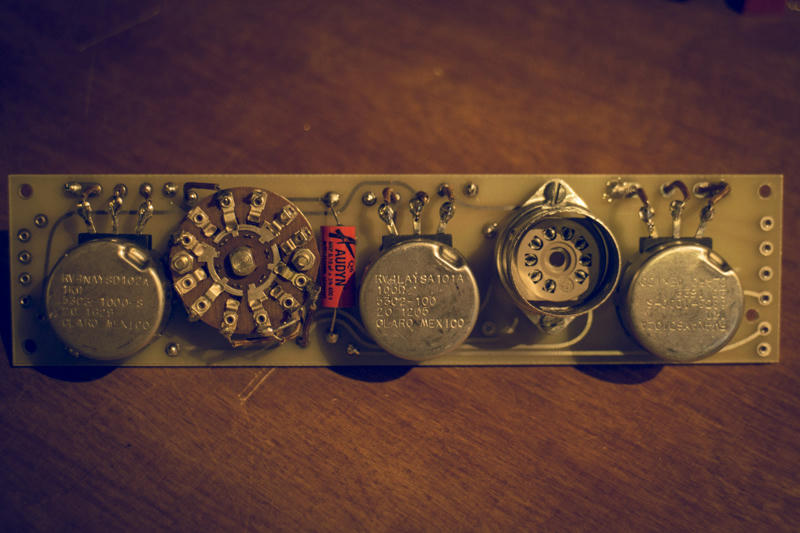
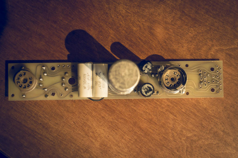
- handmade, authentic re-creations of the 2 original pcbs: these will be handmade to original specs with fork turrets just like the original
- handmade PSU turret board
- handmade RATIO turret board
- handmade METERING turret board
- first BOM
- first wiring layout for the entire unit
All of this I will offer as a kit in this LIMITED run for EUR 399.00 + shipping & PP
Actually this is the price if we can reach 50 chassis, but I convinced all suppliers - if we don't hit that margin, but only 40 chassis instead, we'll still get that price")
And I'm positive that we can reach 40pcs.
And in case we end up with only 38pcs, I will have to buy one for Mom and one for Granny - I'm sure they'd love them ;D
SO:
I'll get in touch with all of those who posted here and want to have one or two or...
In case you're new to this thread and interested send me an email to [email protected]
If you posted here and don't get an email within the next couple of days, do the same
As in the past - I'll collect the funds for the group buy - and after I received your payment you'll be added to the list here.
Lead time for having these gems manufactured will be around 6-8 weeks.
AGAIN: I'll keep this group buy open until March 15th - after that deadline I'll process the orders and have the kits manufactured...
Currently it looks like as if most people want to use API 361 meters (which is the one I used for my prototype) - and forum member moltenwok posted that a friend of his has more than 30 of these available. But they also turn up on eBay fairly often and are actually cheaper than a new SIFAM meter.
But I optionally I can also do a version designed for the SIFAM R32AF meter which is still readily available...
For further discussion and details go to page 8 (and onwards)
GROUP BUY LIST:
kosi 2 [paid]
Shaker-her 1 [paid]
JMarcovis 2 [paid]
TubeMonkey 1 [paid]
damiangiannis 1 [paid]
Phrazemaster 2 [paid]
mro 1 [paid]
moltenwok 4 [paid]
59flame 1 [paid]
ilfungo 1 [paid]
Salomonander 2 [paid]
Craig 1 [paid]
mohausler 1 [paid]
LeRoux 1 [paid]
Adadan 1 [paid]
BramK 1 [paid]
Jeanpierreisyou 1 [paid]
core 13 3 [paid]
Donnie Darko 2 [paid]
Bubbie 2 [paid]
Quayhog 2 [paid]
dbonin 1
wmarden 1 [paid]
Faby 1 [paid]
nickhepfer 1 [paid]
Taoma 1 [paid]
Jefepeters 1 [paid]
Jmcc 1 [paid]
zumwalt 2 [paid]
diylan [paid]
xarolium 2 [paid]
artur 1 [paid]
potato cakes 2 [paid]
spaceyjb 1 [paid]
Marc O 1
Alex64bit [paid]
+++++++++++++++ original post ++++++++++++++++
Hey guys,
those of you who are familiar with my chassis work know, I always work with great love for detail when approaching a project.
For those who don't know my chassis: https://groupdiy.com/index.php?topic=63423.0
Here in Germany we have a saying that says "Ganz oder gar nicht" which is pretty much the same as "Go big or go home!"
(Maybe that's the basic core of what people commonly call "German engineering" hehe ;D)
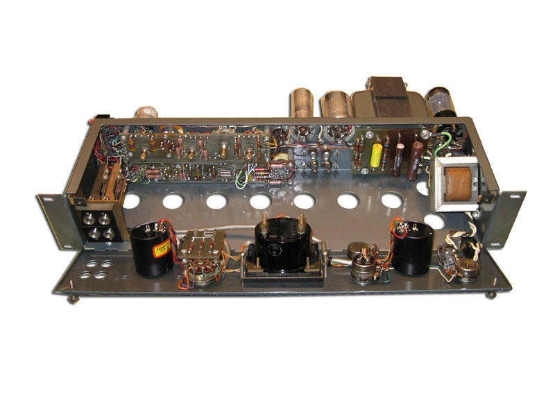
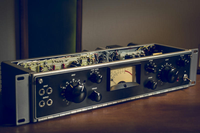
Anyway, I actually wanted to start a UA 176 vari-mu project more than 5 years ago, but as I always found it more challenging to find out about how original pieces of gear work, how they were built and faithfully recreating them rather than buying a pcb (if available) and a generic enclosure to make some kind of a clone, the UA 176 was not easiest project to tackle.
But after gathering quite some experience with other chassis projects over the past years, and people keeping on bugging me to do the 175b or 176 I thought ok let's do it - properly!
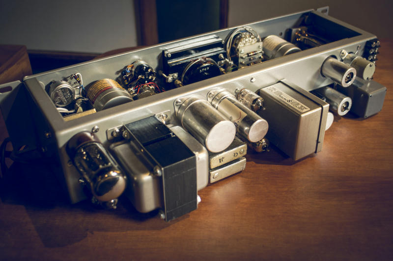
That means faithfully recreating the original chassis work, the original pcbs, the original turret boards etc.
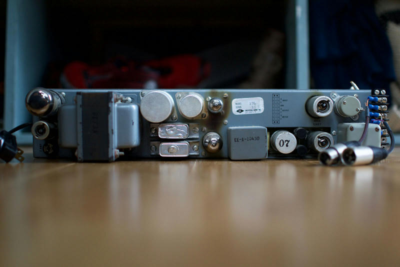
First step: designing & manufacturing the prototype chassis
I'll post more pics and updates in the next couple of days and then some more as the project evolves
If you want to share your thoughts, you're welcome to do so and if you just want to know how it all turns out, subscribe to this thread.
If all goes well I plan to do a small run of UA176 kits that include the chassis, pcbs, turret boards and a build manual for recreating on of these gems for yourself
GROUP BUY IS CLOSED NOW
I pasted the info here in this first post, so you don't have to search for it
Here's what will be included in this authentic re-creation of a UA 176 chassis kit:
- main chassis, bent, welded, smoothed and powder coated grey
- first front panel - also folded edges, welded smoothed and powder coated grey
- custom made hinge manufactured following original specs, powder coated and welded to the first front panel
- second front panel to go on top of the first one: this will be the black panel with white silk-screening
- custom made stainless steel thumb screws designed for original looks
- mounting bracket for input/output jacks on the front
- mounting bracket for optional metering switch inside
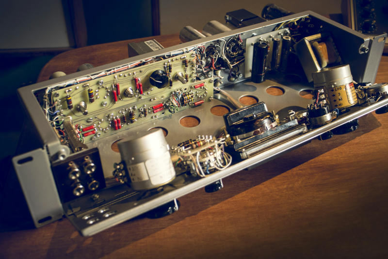
- handmade, authentic re-creations of the 2 original pcbs: these will be handmade to original specs with fork turrets just like the original
- handmade PSU turret board
- handmade RATIO turret board
- handmade METERING turret board
- first BOM
- first wiring layout for the entire unit
All of this I will offer as a kit in this LIMITED run for EUR 399.00 + shipping & PP
Actually this is the price if we can reach 50 chassis, but I convinced all suppliers - if we don't hit that margin, but only 40 chassis instead, we'll still get that price
And I'm positive that we can reach 40pcs.
And in case we end up with only 38pcs, I will have to buy one for Mom and one for Granny - I'm sure they'd love them ;D
SO:
I'll get in touch with all of those who posted here and want to have one or two or...
In case you're new to this thread and interested send me an email to [email protected]
If you posted here and don't get an email within the next couple of days, do the same
As in the past - I'll collect the funds for the group buy - and after I received your payment you'll be added to the list here.
Lead time for having these gems manufactured will be around 6-8 weeks.
AGAIN: I'll keep this group buy open until March 15th - after that deadline I'll process the orders and have the kits manufactured...
Currently it looks like as if most people want to use API 361 meters (which is the one I used for my prototype) - and forum member moltenwok posted that a friend of his has more than 30 of these available. But they also turn up on eBay fairly often and are actually cheaper than a new SIFAM meter.
But I optionally I can also do a version designed for the SIFAM R32AF meter which is still readily available...
For further discussion and details go to page 8 (and onwards)
GROUP BUY LIST:
kosi 2 [paid]
Shaker-her 1 [paid]
JMarcovis 2 [paid]
TubeMonkey 1 [paid]
damiangiannis 1 [paid]
Phrazemaster 2 [paid]
mro 1 [paid]
moltenwok 4 [paid]
59flame 1 [paid]
ilfungo 1 [paid]
Salomonander 2 [paid]
Craig 1 [paid]
mohausler 1 [paid]
LeRoux 1 [paid]
Adadan 1 [paid]
BramK 1 [paid]
Jeanpierreisyou 1 [paid]
core 13 3 [paid]
Donnie Darko 2 [paid]
Bubbie 2 [paid]
Quayhog 2 [paid]
dbonin 1
wmarden 1 [paid]
Faby 1 [paid]
nickhepfer 1 [paid]
Taoma 1 [paid]
Jefepeters 1 [paid]
Jmcc 1 [paid]
zumwalt 2 [paid]
diylan [paid]
xarolium 2 [paid]
artur 1 [paid]
potato cakes 2 [paid]
spaceyjb 1 [paid]
Marc O 1
Alex64bit [paid]
+++++++++++++++ original post ++++++++++++++++
Hey guys,
those of you who are familiar with my chassis work know, I always work with great love for detail when approaching a project.
For those who don't know my chassis: https://groupdiy.com/index.php?topic=63423.0
Here in Germany we have a saying that says "Ganz oder gar nicht" which is pretty much the same as "Go big or go home!"
(Maybe that's the basic core of what people commonly call "German engineering" hehe ;D)
Anyway, I actually wanted to start a UA 176 vari-mu project more than 5 years ago, but as I always found it more challenging to find out about how original pieces of gear work, how they were built and faithfully recreating them rather than buying a pcb (if available) and a generic enclosure to make some kind of a clone, the UA 176 was not easiest project to tackle.
But after gathering quite some experience with other chassis projects over the past years, and people keeping on bugging me to do the 175b or 176 I thought ok let's do it - properly!
That means faithfully recreating the original chassis work, the original pcbs, the original turret boards etc.
First step: designing & manufacturing the prototype chassis
I'll post more pics and updates in the next couple of days and then some more as the project evolves
If you want to share your thoughts, you're welcome to do so and if you just want to know how it all turns out, subscribe to this thread.
If all goes well I plan to do a small run of UA176 kits that include the chassis, pcbs, turret boards and a build manual for recreating on of these gems for yourself