You are using an out of date browser. It may not display this or other websites correctly.
You should upgrade or use an alternative browser.
You should upgrade or use an alternative browser.
GROUP BUY: Universal Audio 176 - a 100% faithful recreation of a legend! CLOSED!
- Thread starter rainton
- Start date


Help Support GroupDIY Audio Forum:
This site may earn a commission from merchant affiliate
links, including eBay, Amazon, and others.
salomonander
Well-known member
- Joined
- Aug 28, 2011
- Messages
- 951
sweet. what choke did you use for the build?
rainton
Well-known member
gyraf said:...beautiful work...
Thanks gyraf - I really appreciate it
")
kosi said:We can ask the guys from authenticaos, wether they roll us some special ones ! I will send a mail
Great idea kosi!
salomonander said:sweet. what choke did you use for the build?
I used a Triad C-7X, but you could also use a Hammond 158M I guess.
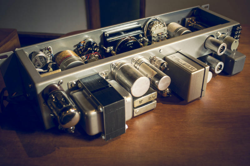
Finally the pcbs are mounted and I already started to wire them up - now it gets really exciting!
What is coming together in front me now physically resembles what I studied on pics only the last couple of months
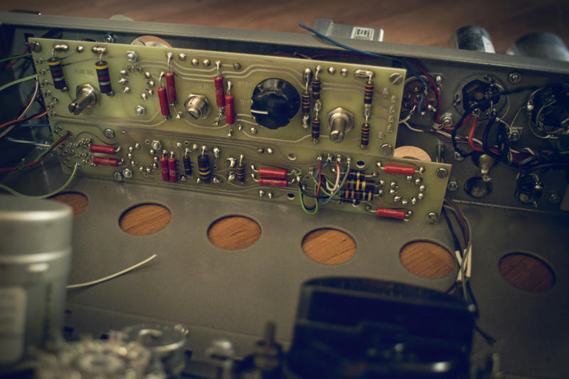
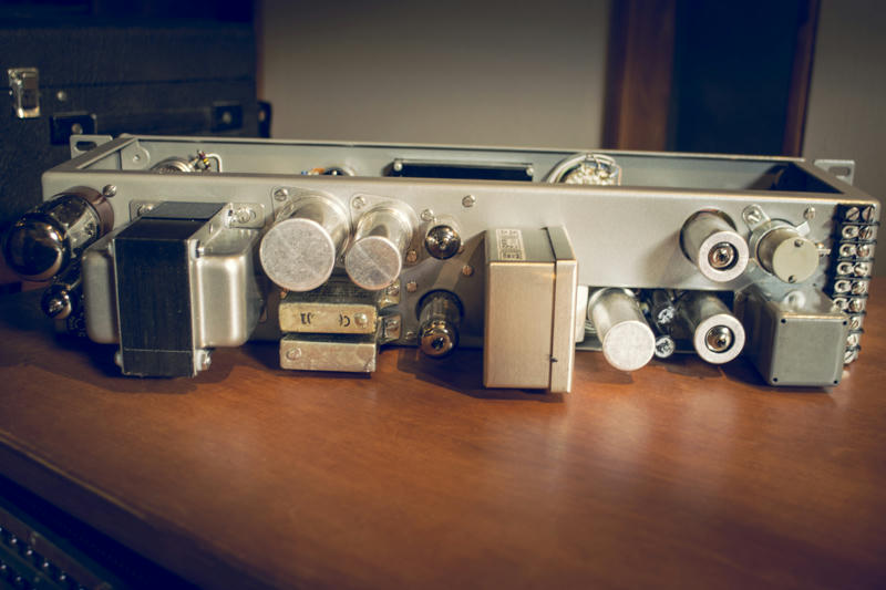
And from the back it also looks exactly as it should - all tube sockets are in the right positions - only the Sowter transformer
makes the difference...

KrIVIUM2323
Well-known member
Hi, reeally nice work.
What reference of switch you used for ratio selection? Where is it availlable?
What reference of switch you used for ratio selection? Where is it availlable?
rainton
Well-known member
KrIVIUM2323 said:Hi, reeally nice work.
What reference of switch you used for ratio selection? Where is it availlable?
Well, the schematics ask for a 3pole 4 pos switch - which are easy to find.
What is a little harder to find is such a switch with all poles and positions located on only one wafer, as used
in the vintage units.
I found one - it's a Centralab PA-2006, but there's enough space behind the switch to use a 2 wafer switch as well.
So no need to worry - plenty of choices. The Centralabs appear on eBay regularly, and they are also available at tedss.com, but they are not cheap there...

![Soldering Iron Kit, 120W LED Digital Advanced Solder Iron Soldering Gun kit, 110V Welding Tools, Smart Temperature Control [356℉-932℉], Extra 5pcs Tips, Auto Sleep, Temp Calibration, Orange](https://m.media-amazon.com/images/I/51sFKu9SdeL._SL500_.jpg)


rainton said:Also visible in the pics of the original unit is the bracket that holds the 1/4" jacks on the left side.
Obviously these connectors allowed for patching the comp into any other piece of gear directly, while the unit also has a barrier strip type terminal on the back for wiring it up a patchbay...
The jacks are mono switching 1/4" inch - so as soon as something plugged in there, the input and/or output on the back is disconnected.
Feeding a piece of gear with a balanced signal through 2 mono jacks seems kind of weird though ;D
Actually these jacks were common in telephone equipment. They used a single plug body with two prongs and a single cable, see photo below.
Attachments

rainton
Well-known member
Thanks guys!! And sorry for the lack of updates - the last couple of weeks were extremely busy.
But today I finally made some progress.
Thanks mjrippe - great info! Now it all makes sense ;D
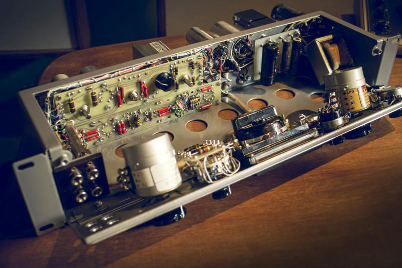
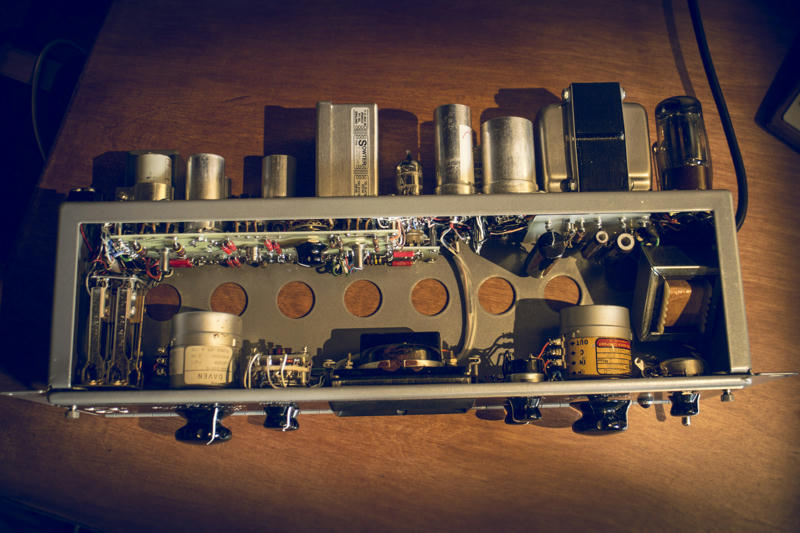
Now the updates: I finally wired up the pcbs & transformers, as well as the screw-terminal & the 1/4" connectors:
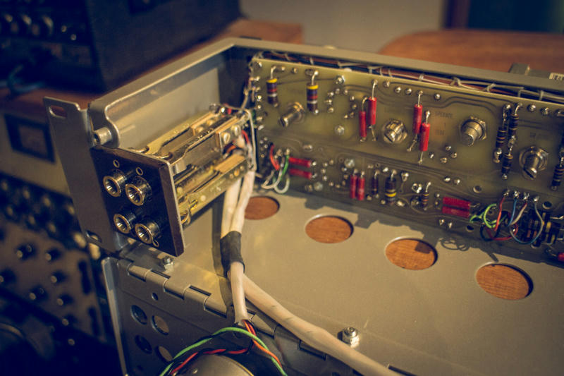
As you can see on the pic, I found a piece of Bakelite from an old connector panel in my workshop, so I simply couldn't resist and added a small Bakelite panel to the front of the connector bracket as featured by the original units
I also started to tie up the wires routed along the upper edge of the pcbs as done in the 60s (it's my first attempt on this technique, so please bear with me)
Beyond that I wired up most of the front panel - except for the ratio switch and the meter. In the next pic you can also see the wires coming from the output transformer for the ratio circuit:
I'm not quite sure yet how to deal with the ratio circuit - I found very little information on that, and the only pics I found, showed different layouts. The same goes for the meter circuit. In the 175b the turret board for the meter circuit is mounted to the back of the meter switch. But in the 176 the ratio switch takes the position of the meter switch on the front panel - and thus, the ratio turret board is mounted to the back of that switch.
I found pics where the meter switch was mounted to the right vernier pot with the help of a bracket, with the meter turret board mounted to bottom of the chassis. If any of you have more info on that I'd be grateful.
If not I'll find a way to solve it
Apart from that it seems the VU meter is not illuminated ? There's no space for a lamp holder, and all pics of 175bs or 176s I found show now lamp above the meter. The only thing that could fit would be a fuse type lamp. What do you think?
But today I finally made some progress.
mjrippe said:Actually these jacks were common in telephone equipment. They used a single plug body with two prongs and a single cable, see photo below.
Thanks mjrippe - great info! Now it all makes sense ;D
Now the updates: I finally wired up the pcbs & transformers, as well as the screw-terminal & the 1/4" connectors:
As you can see on the pic, I found a piece of Bakelite from an old connector panel in my workshop, so I simply couldn't resist and added a small Bakelite panel to the front of the connector bracket as featured by the original units
I also started to tie up the wires routed along the upper edge of the pcbs as done in the 60s (it's my first attempt on this technique, so please bear with me)
Beyond that I wired up most of the front panel - except for the ratio switch and the meter. In the next pic you can also see the wires coming from the output transformer for the ratio circuit:
I'm not quite sure yet how to deal with the ratio circuit - I found very little information on that, and the only pics I found, showed different layouts. The same goes for the meter circuit. In the 175b the turret board for the meter circuit is mounted to the back of the meter switch. But in the 176 the ratio switch takes the position of the meter switch on the front panel - and thus, the ratio turret board is mounted to the back of that switch.
I found pics where the meter switch was mounted to the right vernier pot with the help of a bracket, with the meter turret board mounted to bottom of the chassis. If any of you have more info on that I'd be grateful.
If not I'll find a way to solve it
Apart from that it seems the VU meter is not illuminated ? There's no space for a lamp holder, and all pics of 175bs or 176s I found show now lamp above the meter. The only thing that could fit would be a fuse type lamp. What do you think?


rainton
Well-known member
Well many of the 175bs and even some 176s had the API 361 meter - but without the lamp holder bracket.
For my prototype I also used the API 361 meter and I think it's gorgeous!
But if we can gather enough interest to do a run of chassis, I would most likely go with the SIFAM R-32AF meter, since it's still readily available. Also it can be ordered with a lamp holder that utilizes a fuse type lamp and could indeed fit the chassis. It's slightly larger than the original, but very close to the weston meters that were used in later units...
If some of you want to use the the API 361 meter, I could do some special edition chassis for the group members interested.
What do you think?
Regarding using a lamp together with the API meter I would indeed try to find a solution with a custom mounted fuse type lamp.
The lamp would need to have some kind of cover from above though, since the chassis has no lid - or it will lighten up the entire rack ;D
I would like to have a special edition chassis for the 361. Oh wait, I take 2 !
In real life, I actually don't need an illuminated meter, but I have a daylight studio.
I thought about the lid situation. Why did they build the units without lid ? Maybe to simply reach the internal pots more easy ? Because they were needed so often ? Really mysterious. When you have to change settings all the time, it's good to have no lid. When it's about one set and forget, I think, it'S better to have a lid. Case closed
rainton
Well-known member
kosi said:I would like to have a special edition chassis for the 361. Oh wait, I take 2 !
In real life, I actually don't need an illuminated meter, but I have a daylight studio.
I thought about the lid situation. Why did they build the units without lid ? Maybe to simply reach the internal pots more easy ? Because they were needed so often ? Really mysterious. When you have to change settings all the time, it's good to have no lid. When it's about one set and forget, I think, it'S better to have a lid. Case closed
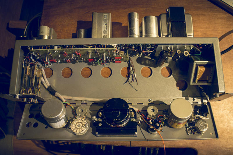
True about the lid. Well I also thought it might have been their ultimate design approach to get as much heat out of this thing as possible. Taking a look at some spots it seems this thing runs rather hot. This would also explain the huge holes all across the bottom of the unit - they're so weirdly placed with no real logic at all. I wondered what they had smoked when designing it...but I designed my unit exactly the same way hahaha! ;D
salomonander
Well-known member
- Joined
- Aug 28, 2011
- Messages
- 951
Please a run for the api meters as i also purchased my pair already. They are not that hard to find. I commit to a pair no problem. Cheers
Phrazemaster
Well-known member
I third that request - I just got an API 361 meter too and would like the faithful special edition chassis. I would be in for 1.
Also, will you make boards available too?
Thx,
Mike
Also, will you make boards available too?
Thx,
Mike
rainton
Well-known member
Got you guys ;D
I'm extremely proud that after a pretty bumpy ride in finalizing my prototype I can finally announce: THE LEGEND IS BACK - ALIVE!! ;D
Last week, after being pretty much finished with the build I spent a lot of time debugging as it seems there were some errors in the original pcb layout as well as in the schematics + some additional errors on my prototype pcb that gave me a pretty hard time getting this wonderful compressor up & running. But now all errors are corrected and the very first 100% faithful recreation of an original UA176 in more than 50 years is now up and singing!
I only put through some samples yet to make sure everything is working correctly, but the experience when I first heard it doing it's thing - I was absolutely stunned!!
The color and vibe it ads to the signal is unbelievable - and frankly I have never heard a compressor that sounds anything like it.
I have to admit though - I haven't heard a vintage 176 or 175b yet, and in my studio I have "only" LA2As, 1176s, LA3As and SSL comps, but this is an entirely different animal! Absolutely amazing!
I have to play around with it a little more - in the meantime here's the beauty in all its glory:
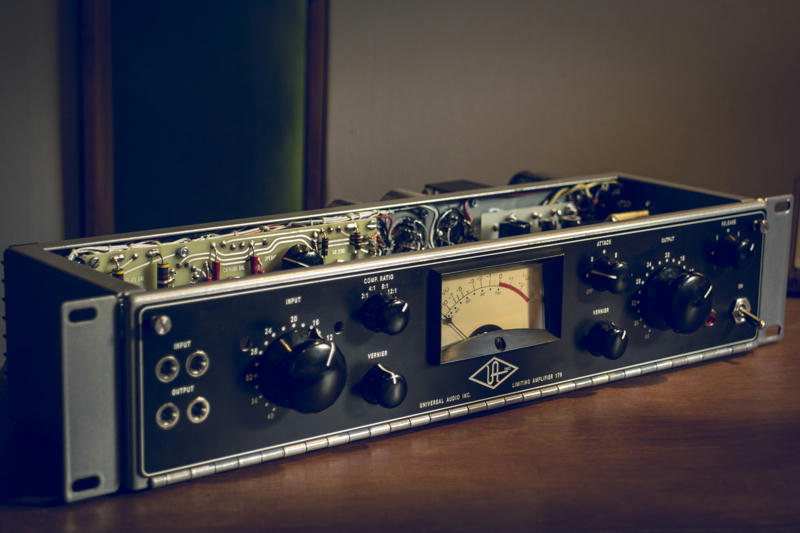
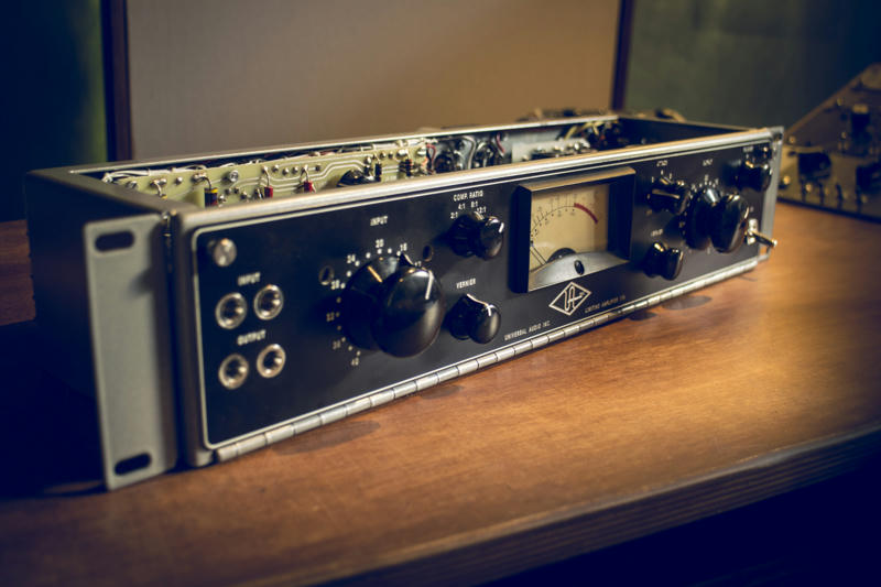
Oh and just for the records - this unit I made for my personal use and the logo is only on there to pay proper respect to the legend going all the way to bring this beauty back to life in every detail when committing to the quest. I hope I'll be forgiven
I'm extremely proud that after a pretty bumpy ride in finalizing my prototype I can finally announce: THE LEGEND IS BACK - ALIVE!! ;D
Last week, after being pretty much finished with the build I spent a lot of time debugging as it seems there were some errors in the original pcb layout as well as in the schematics + some additional errors on my prototype pcb that gave me a pretty hard time getting this wonderful compressor up & running. But now all errors are corrected and the very first 100% faithful recreation of an original UA176 in more than 50 years is now up and singing!
I only put through some samples yet to make sure everything is working correctly, but the experience when I first heard it doing it's thing - I was absolutely stunned!!
The color and vibe it ads to the signal is unbelievable - and frankly I have never heard a compressor that sounds anything like it.
I have to admit though - I haven't heard a vintage 176 or 175b yet, and in my studio I have "only" LA2As, 1176s, LA3As and SSL comps, but this is an entirely different animal! Absolutely amazing!
I have to play around with it a little more - in the meantime here's the beauty in all its glory:
Oh and just for the records - this unit I made for my personal use and the logo is only on there to pay proper respect to the legend going all the way to bring this beauty back to life in every detail when committing to the quest. I hope I'll be forgiven
Phrazemaster
Well-known member
Dany is the godfather of german mic clones.
You sir, are the godfather of compressor and eq clones.
STUNNING!!!
I feel the same way about logos. It's not that I'm trying to pass off the gear as an original - it's that the logo lends a feel to the design that makes it feel/look right. Logo-less clones may be more politically correct, and legally correct, but they are missing that something that gives them the right feel. So I shamelessly put logos on my clone gear for those reasons.
By the way, I had read that this compressor uses a tube with a variable-mu feature, and that this tube is unobtainium.
Also that one of the transformers for the ratios is also unobtainium. How do we get around these issues?
Thanks Rainton!! Your work is MASTERFUL!!!
supersonic
Member
- Joined
- Jul 6, 2017
- Messages
- 23
This is so beautiful :'(
Similar threads
- Replies
- 122
- Views
- 12K
- Replies
- 4
- Views
- 1K
- Replies
- 27
- Views
- 10K