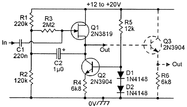
FET input stage for instruments

GroupDIY Audio Forum

Help Support GroupDIY Audio Forum:

This site may earn a commission from merchant affiliate links, including eBay, Amazon, and others.
warpie said:
Thanks, that makes some more sense to me :) Is it too much to ask how do I go about calculating the output impedance (i.e how did you calculate the "few dozen ohms")?
The output Z of the source follower is assumed to be 1-2k (1/gm). The emitter-follower Z is roughly 1/hfe times the source Z. So, hfe being in the 100-500 range, that gives a range of 2-20 for the output Z. In fact probably higher since the FET is operated at very low current.


I would assume that the lower the R6 the higher the headroom but how do I choose the correct value.
This is true up to a point. The quiescent current in the FET being only 70uA, its limited capability to produce negative peaks restricts the RMS current at about 50uA. The resulting output capability at the output of the emitter-follower is hfe times this. Again assuming hfe to be 100-500, the output current is in the range 0.5mA-2.5mA.
Case1: hfe 100. Q3 quiescent current 0.7mA, R6=10k (assuming B+ at 15V  and DC op point at 1/2 B+). Output load 2kohms (many mic inputs are closer to 1.5k). Resulting load 10k//2k=1.66k. 0.5mAac into 1.66k=> 0.8Vrms.
Case 2: hfe 500. Q3 quiescent current 3.5mA, R6=2.16k
Resulting load 2.16//2k=1.04k. 3.5mAac into 1.04k=> 3.6Vrms.
Now this calculation has more shortcuts and approximations than a congressman's speech, so you would be lucky if you approached these figures with less than 50% error.
In conclusion, there is a point where decreasing R6 increases so much the demand on the preceding stage that it becomes counteractive.
 
warpie said:
Are you referring to me or to the OP? :)

I am sorry for not being clear, I was talking about a board for this circuit:
NV_0600_Marston_fig8.jpg


And I've included Q3, I ran it on 12v (or was it 15v? Can't remember which regulators I used on the PSU) and have only used it with active basses (though not extensively, I used it together with my headphone amp).
 
> calculating the output impedance (i.e how did you calculate the "few dozen ohms")?

"Cathode impedance". FET Source and BJT Emitter function like a tube cathode.

For "small" devices: tube and JFET cathodes are about 1K. BJT at common small-audio current is dozens of Ohms.

Tubes/JFETs, determine Gm (transconductance) from the data-sheet *for the expected current*. Note that makers tend to use show-off currents much larger than we use in small audio. Great exactness is not needed because a 4:1 change of current is typically a ~~2:1 change of Gm. Now figure 1/Gm, which is the cathode resistance (impedance). And nearly all small tubes and JFETs at small-audio currents run 500-1500r. Fat 6V6 at 40mA may be 200r.

A BJT at 1mA, low-Z drive, the "cathode" is 26 Ohms. Shockley's Law. It is inversely proportional to current, so at 10mA we have 2.6 Ohms. There's always some drive impedance, and strays, and I am lazy, so I use "30 Ohms". If we figure this plan runs the BJT Emitter at half supply voltage, with 7K emitter resistor, 10V/7K is 1.4mA, so 30r/1.4= 22 Ohms.

Plus whatever ELSE is going on. Naked emitter followers into cables oscillate-- you should put ~~100r in series (so now 122r Zout). This BJT sees a FET source ~~1K, which divides by hFE, which may be 200, so that's another 5 Ohms. NFB (none here) can be rigged to reduce OR increase output impedance.
 
Thank you gents! I'll read your posts a few times to digest it and hopefully to clear things up!  :)

Just one last thing. As far as I understand this circuit can happily drive both passive and active pickups. Is that correct?

Thanks again.
 
Ummm... you don't "drive pickups" in audio. (In Maine and Texas, hell yeah, the bigger the bettah.)
 
warpie said:
As far as I understand this circuit can happily drive both passive and active pickups. Is that correct?
Yes, can do both, but only on those guitars with an 'input' jack.

Most proper guitars have an 'output' jack though... 

... and then there are those ads where the photographer has placed the vibrato handle in the jack-output  :p

OK, sorry, couldn't resist (it's beyond me why some people call it input).

The serious answer: Yes, suited for both, will work, but no need for this Hi-Z buffering with 'active pickups' (which are in fact passives with already a buffer slammed on)

Bye


Latest posts

Back
Top