Help with modifying Circuit please

GroupDIY Audio Forum

Help Support GroupDIY Audio Forum:

This site may earn a commission from merchant affiliate links, including eBay, Amazon, and others.

sonolink

Well-known member
Joined
Feb 15, 2010
Messages
1,257
Location
London-Madrid
Hello everybody

I am trying to modify a guitar preamp circuit, adding some switches to create different distortions or channels.
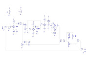
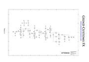
This is the original schem by GrindFX:


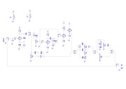
This is my modded schem:


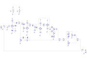
I've added True Bypass Switch and Clean/Crunch/Lead Channels.

My main questions are about the 22n Caps connected to the plate resistors:
1-should they go before the switch (as C3) or after (like C5)?
2-should C13 go after SW4.B? SW4 is supposed to allow the player to choose to place the preamp in front of an amp (through 100k pot) or in its FX loop (through Presence circuit and 1M pot)

Plate voltages are 190V unloaded.
Thanks in advance for your time and help
Cheers
Sono

 
sonolink said:
My main questions are about the 22n Caps connected to the plate resistors:
The 22n caps are there to block DC voltage. You need to understand and analyze the circuit before you add switches. For several reasons, like safety (you probably don't want 190V on a switch) and whether the switch will pop and blow your speaker from a large DC voltage jump. Generally you want the switches to be where the DC voltage is 0v.

You have a triode gain stage (v1a v1b) and a DC coupled cathode follower (V2). The triode gain stage has  a high voltage on the plate and uses the 22n cap to block that voltage from the grid of the next stage.  The DC coupled cathode follower, however, uses the plate voltage of the 1st triode to bias the 2nd stage, with the output off the cathode. 
You can read about these basic circuits and understand the voltages at the different plates.

With SW3 you are bringing the cathode follower a stage earlier  and switching a pretty high voltage. That looks like a bad idea.

I'd suggest you read a lot more about tube gain stages before building anything. There are a lot of amps with switching so search for schematics for ideas of how to do it safely. And it might not be a bad idea to work on a low voltage transistor pedal first instead of tubes. Once you get that working, move on to tubes.
 
Hi Dmp

Thanks for taking the time to check the schems and for your reply :)

I have built many tube amps and pedals, although this is the very first time I try to mod one. 
I am generally very cautious (you're never safe enough) and love electronics. I wish I knew more about it although I try to learn as much as I can. That's the reason why I post here. I have learned quite a bit from this forum :)
I will check through everything you say and try to come up with a solution or a different approach.

dmp said:
With SW3 you are bringing the cathode follower a stage earlier  and switching a pretty high voltage. That looks like a bad idea.
What is the bad idea? Bringing the cathode follower a stage earlier, switching a pretty high voltage? Or both? :)
If high voltage is the problem wouldn't a 250VDC capable switch be a solution?
I suppose you are aware of this, but the idea behind this switch is to have different levels of distortion, of course

Again, I appreciate your time and help :)
 
sonolink said:
What is the bad idea? Bringing the cathode follower a stage earlier, switching a pretty high voltage? Or both? :)
I suppose you are aware of this, but the idea behind this switch is to have different levels of distortion, of course
I think the DC coupled cathode follower should be left alone, since I'm don't think you could switch the DC without putting high voltage on the switch and a loud pop. This means leaving V2A & B unswitched.
If you want to reduce gain, you would probably want to switch out the gain stage, v1a perhaps. But you should do some research as I haven't built an amp that does switching out gain stages.  There are a lot of schematics around that have switching in them. You just need to do a lot of research.

For instance, if you scroll down the page here:
https://el34world.com/Hoffman/files/Hoffman_Plexi50.pdf

You'll see a 'hot switch' schematic that switches an extra gain stage in and out of a plexi style preamp. Notice the DC coupled cathode follower is left alone and the relay switch operates on places of the circuit that are at 0v DC
 
How about this?


Is that better? Maybe I'm missing out some DC blocking cap? Thanks again for that link. Great piece of document, layout included :)

Cheers
Sono
 
The switches look better for DC voltage issues.

Do you expect to be able to get similar levels as you switch?  Because I'm not sure you'll be able to do that.

And do you want the tone stack to only affect the 'dirty' channel? Seems you might like a tone stack on the clean channel as well. fwiw.

 
dmp said:
The switches look better for DC voltage issues.
Excellent! Thanks 8)

dmp said:
Do you expect to be able to get similar levels as you switch?  Because I'm not sure you'll be able to do that.
The Gain Pot controls both "dirty" stages so I don't know how much difference there will be between the 2 but if the difference is HUGE maybe it could be compensated with some fixed resistor? Just a guess...
I would hope it to be the usual difference between a crunch and a lead channel, but I won't know until I fire it up I guess :)

dmp said:
And do you want the tone stack to only affect the 'dirty' channel? Seems you might like a tone stack on the clean channel as well. fwiw.
Oooooops, thank you for pointing that out! Geez... I'm not at home so I can't redraw the schem right now but I guess I should place the tone stack between SW3 and SW2 right?

Thanks again for your time and help mate ;)
Cheers
Sono

 
I was thinking of using this bypass switch for all the switching except the impedance matcher (SW2) but I just realized I won't be able to use it to switch from Clean to "Dirty", right? :(


If so will a Stomp DPDT switch make noise when switching and is there a fix for that? It has to be a Stomp switch because this thing is to be built inside a pedal...

Cheers
Sono
 
Thanks for your input PRR.

PRR said:
3P2T switches are now common in stomp-world.

Thanks for your input PRR.
I'm aware of that, but won't I have popping noises?
I guess it's not possible to use a DPDT for that unless I give up the LED right?

Cheers
Sono

 
> won't I have popping noises?

Popping is a very different problem, not about the number of poles.

In any case, the total cost is like buying a lunch. Build it, try it, don't over-think in advance.
 
PRR said:
Popping is a very different problem, not about the number of poles.

Sorry for the misunderstanding, I didn't mean it like that. It was 2 different questions really. Just trying to learn and understand.
Anyway I'll build it and see if it pops or not. Thanks.

Cheers
Sono
 
If you want the same 'plexi' sound in the dirty and clean channels, then the tone stack should be driven by the cathode follower in both channels.
 
dmp said:
If you want the same 'plexi' sound in the dirty and clean channels, then the tone stack should be driven by the cathode follower in both channels.

Ok. So I've read a bit about what a cathode follower is and I think I see what you're saying. If I understand you correctly, basically in the schem as it is, the tone stack when in Clean channel, is driven by V1A Anode, whereas when in Dirty channel, it'll be driven by the Cathode of V2B.

According to what I've understood from my reading, a cathode follower is a unity-gain stage placed between the preamp stages and the tone stage to buffer them from each other. It provides the ability to source extra current to drive the tone stack and won't add any gain (since it's unity gain). Originally I took the "Clean Channel" from the Matchless HotBox: http://diy-fever.com/wordpress/wp-content/uploads/2009/12/tube_reactor.gif
In that schem the design gives up the tone stack for the Clean channel, but as I'm a complete ignorant in designing I didn't even realize that. Thanks to you I know a tiny bit more about the amps I build for a hobby :)
My first thought was to place the Gain pot after V1A cathode, but something told me that's wrong and I should look at things the other way around. So, I imagine the switching should occur in a different place to keep the tone. How about this? I've added a cap before V2B's grid to block any DC coming from pin1. Am I right?


Cheers
Sono
 
Back
Top