sonolink
Well-known member
Ok. I'll read the article and report back ")
Cheers
Sono
Cheers
Sono


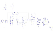
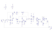
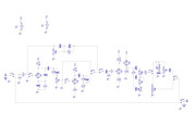
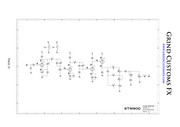
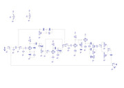
This circuit is essentially a preamp in a stompbox that can be put in front of the preamp of an amp. In such position it is going to add many gain stages in front of however many gain stages the amp already has and it’s going to be LOUD. OR it can be plugged into a power amp or into the return of an amp’s loop (bypassing the internal pre)...abbey road d enfer said:I have to say the way the tone stack is loaded with a 25k presence pot is quite surprizing. However, it seems it should do what it is intended to do, except it attenuates the signal by about 15dB. Is it intended? I don't know...
Ok. I thought R18 would compensate for gain as a 1M pot half way. Maybe I should convert it into a 1M pot then? Or the whole R17/R18/C16 cluster is wrong? ???abbey road d enfer said:Now, SW3 bypasses one stage and there is no way to compensate the gain difference. I would think a pot at the output of V1b would be desirable.
Ooops, maybe I should have put C1/22nF-R4/1M-R3/1K between SW4.B1 and V2A's grid? Like so:abbey road d enfer said:Also SW4A1&B1 switch the grids, which don't have a grid leak, so you can expect a huge pop when switching.
I understand all that, but my concern is that when you bypass it (going through the pot IMP-Matcher) there is a possivle huge level bump.sonolink said:This circuit is essentially a preamp in a stompbox that can be put in front of the preamp of an amp. In such position it is going to add many gain stages in front of however many gain stages the amp already has and it’s going to be LOUD. OR it can be plugged into a power amp or into the return of an amp’s loop (bypassing the internal pre)...
This is where the presence control comes into play: it will probably be a bit bright when used as a stomp. The presence trimmer can be used to dial this back. As a pre the power stage is likely going to deal with the brightness of the pre so it can be turned up or just tweaked to taste.
Gain around V1b is about 8-9. If you want to compensate, you need a divider of about the same. I would say 470k/68k. Remember that an audio pot at mid-rotation attenuates by about 20dB (10:1).I thought R18 would compensate for gain as a 1M pot half way. Maybe I should convert it into a 1M pot then? Or the whole R17/R18/C16 cluster is wrong? ???
Yes, but you don't need C1.Ooops, maybe I should have put C1/22nF-R4/1M-R3/1K between SW4.B1 and V2A's grid?
Yes, and again you don't need the cap.And replicate C1/22nF-R4/1M-R3/1K between SW4.A1 and V1A's grid?
abbey road d enfer said:I understand all that, but my concern is that when you bypass it (going through the pot IMP-Matcher) there is a possivle huge level bump.
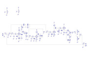
Not yet. I was about to build a proto when DMP forum member brought up some points that I corrected. Initially the Clean channel didn't have a tone stack, like the original circuit schem:abbey road d enfer said:Have you really tested the circuit with the presence pot?
You mean the whole tone stack or just the Bass control?abbey road d enfer said:My sim shows that the Treble control acts as a "rocker" between bass and treble, which may be acceptable, but the Bass control acts more or less like a switch, with the variation concentrated on the first percent of rotation.
IMO this circuit should be placed at the anode of V2A, with a 500k pot and a 1nF cap.
Indeed, but the Marshall/Fender tone stack is meant to be loaded with a rather high impedance, typically 1 Megohm. You load it with 25 k. That makes it behave badly.sonolink said:just saying that it seems to be a known circuit and that it sounds great.
abbey road d enfer said:Indeed, but the Marshall/Fender tone stack is meant to be loaded with a rather high impedance, typically 1 Megohm. You load it with 25 k. That makes it behave badly.
I already answered that: "IMO this circuit should be placed at the anode of V2A, with a 500k pot and a 1nF cap."sonolink said:I see what you mean....that's no good. I downloaded Duncan's Tone Stack Calculator and loaded the Marshall Tone Stack. When I input 25K as Load Resistance (I understand that that would be the Presence trimmer) I see what you mean by bass control acting as a switch. I think thta originally GrindFX put that 25K trimmer there to be able to adjust the brightness produced when the stompbox is in front of an amp's preamp but then again, maybe that's not the best approach?
Any suggestions? Or maybe I should just build a proto and see?
Cheers
Sono
abbey road d enfer said:I already answered that: "IMO this circuit should be placed at the anode of V2A, with a 500k pot and a 1nF cap."
What hiss? These 470pF will ruin the response, for no sensible gain.sonolink said:added 10K grid stoppers with a 470pF cap to ground to avoid hiss
C10 is necessary for the presence control to work. C11 may be there to isolate DC coming from the outside. Just guessing...I wonder why the original GrindFX schem has C10 and C11 for...
It would change the input stage's HF response, in an insignificant way.Would changing the 68k input resistor to 33K change something? Gain I suppose?
abbey road d enfer said:What hiss? These 470pF will ruin the response, for no sensible gain.
OK, So the if the cap is placed before or after the Presence circuit doens't make a difference except for blocking DC when it's before?abbey road d enfer said:C10 is necessary for the presence control to work.
Wouldn't my modded circuit benefit from that? Or it doesn't really matter or affects tone? Or in other words I'd like to understand why you told me I don't need itabbey road d enfer said:C11 may be there to isolate DC coming from the outside. Just guessing...
I can't wait for itabbey road d enfer said:It would change the input stage's HF response, in an insignificant way.
I think you should melt some solder soon.


![Soldering Iron Kit, 120W LED Digital Advanced Solder Iron Soldering Gun kit, 110V Welding Tools, Smart Temperature Control [356℉-932℉], Extra 5pcs Tips, Auto Sleep, Temp Calibration, Orange](https://m.media-amazon.com/images/I/51sFKu9SdeL._SL500_.jpg)


