Bernardo
Well-known member
- Joined
- Dec 8, 2019
- Messages
- 186
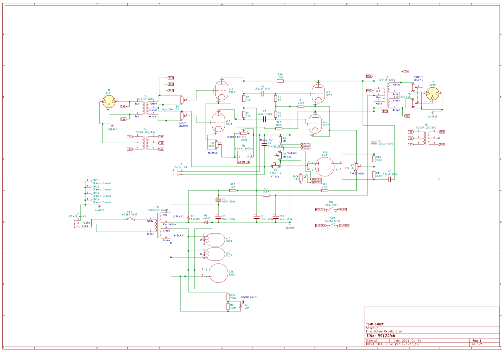
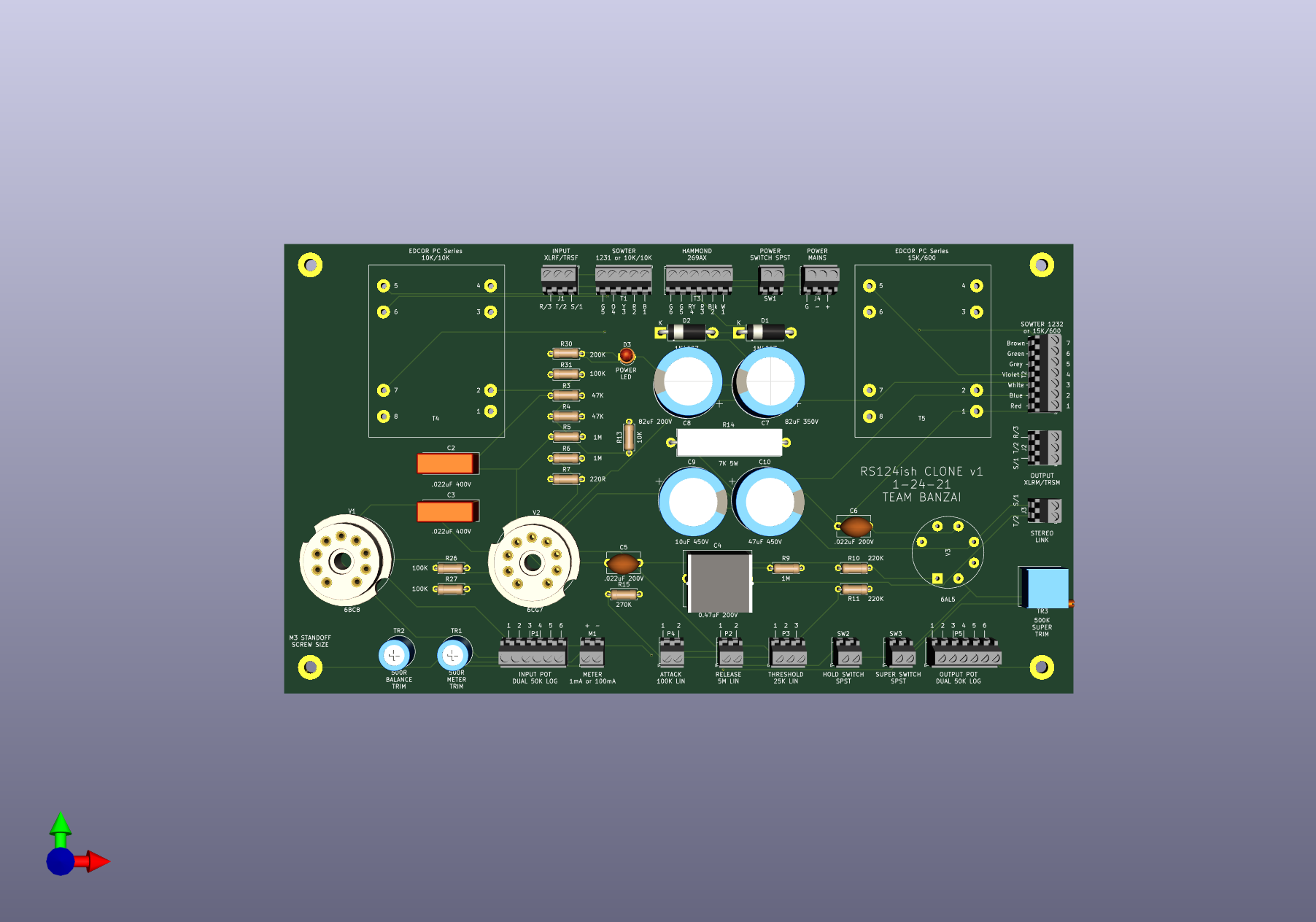
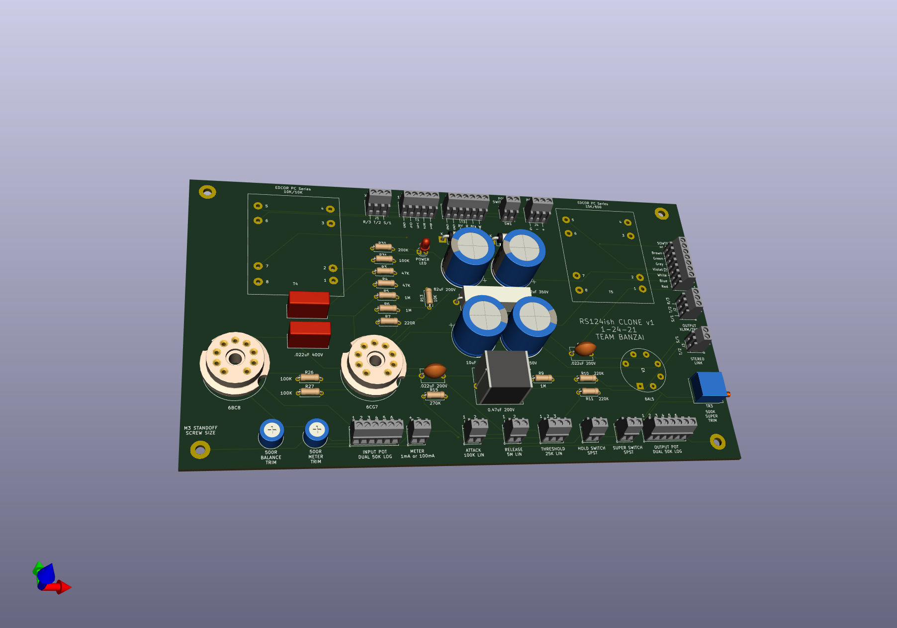
I have finished the 436c, from my humble opinion it has disappointed me, I do not see it more useful than the amplification one.
It is true that I have no experience with varimu compressors but I imagine more of an optical type compression, but I see that this compressor is even more subtle, so I started by completely rectifying the 120v winding and adding the two 100k resistors , All the ground noise has gone, now it sounds without noise, I have left the 1M potentiometer, which I did not notice any use.
According to the scheme that Mr. Winston published, a hold is added (I think it's a release), an output attenuator is added, and a 3.3m potentiometer. I don't know what it is for?
I don't see that it has an attack, I don't see the threshold either.
suokngo that will be automatic like the optician la2a?

")