Altec 436 / RS124-ish Clone

GroupDIY Audio Forum

Help Support GroupDIY Audio Forum:

This site may earn a commission from merchant affiliate links, including eBay, Amazon, and others.
Rob Flinn said:
I found a cheap R core mains transformer on the net that was a LOT cheaper than the hammond & worked very well.  It was about 30 euros.

Yep, I'd be looking at something like that too.  Nice price. 
I can't say I've ever considered using Hammond myself.  I only mentioned them because it's the brand Teambanzai had specified.

Actually, I'm on the hunt for a good and reasonably priced isolation type (240:240) to use for H.T. supplies myself.  I want electrostatic shields though (primary to secondary & possibly another from the core) which narrows my options.

L.T. from a separate supply, maybe switching?  If not, then something also with a shield and high enough AC to allow for DC regulated.  Bipolar +/- 3.15V 

Whichever way, it won't be torroids as I find they're just too wide-band and easily pass hi freq. mains hash into your unit.  Likewise, they can pass junk from the loop of the secondary, rectifier, and first cap back into the mains. 


Winston O'Boogie said:
The pictures are a little big to be able to view them as a whole on my device but...

A few things that jump out:

To keep hum down you'll need to ground the centre-tap of your heater winding rather than let it just float.  Elevating an AC heater supply by about 25 volts with respect to cathode can help further if needed.  Do that with a divider from the clean H.T. and the  cap bypassed 25V injected at the 6V3 AC C.T.

Looking at the specs of your specified Hammond power transformer (269BX), the HV winding isn't 117VAC but 300C C.T.,  so copying the original Altec voltage doubler will be a no-no.
If you already have that transformer then use a full wave bridge across the whole winding and plan on losing over 150V DC in wasted heat with larger series resistors in the filter banks.
However, if you can, buy the Hammond 269AX instead  with 250V AC C.T.  and you won't need to lose so much DC voltage. 

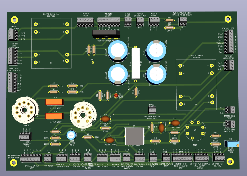
Right on! Input from the man himself. Thank you for the input, the pcb image I posted is still very very early stages, since then I have added much more stuff to the schematic, fixed a few spots. Good catch on the transformer labeling on the schematic. The Hammond I planned to use is the 269AX, think the schematic auto labeled the symbol to a B in the picture, if you notice on the PCB silkscreen it is labeled as the 269AX. Everything in the PCB pic is what would be the alpha build, hence why there are no regular traces and layout is not as thought out as could be.  :D

Later today I will post an updated schematic of what I have down now that I think I fixed some of the problems you pointed out.

Cheers!

 
Altec 436 int20-2.JPG

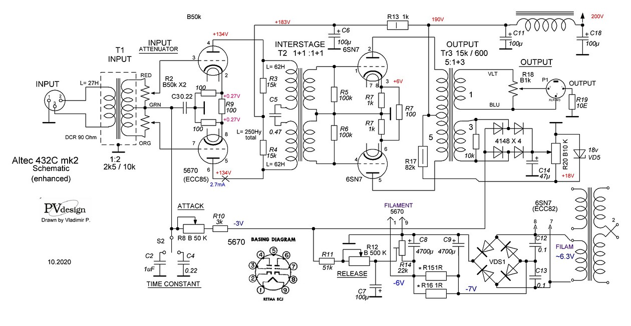
I am mocking up the scheme of my modification Altec 436 mk2, this is an intermediate variation.
  1) Made a special output transformer with winding for the side chain detector
  2) An interstage transformer was manufactured and applied, which solves many problems.
  3) The filament voltage of the first stage is rectified to a constant one, also used for
adjusting the bias of the lamps of the first stage.
You can discuss, please, what someone doesn't like
 

Attachments

  • Altec 436 int20-2.JPG
    Altec 436 int20-2.JPG
    155.9 KB
Here is an updated version of my schematic. Added in switches to select between variable and fixed attack and release pots. I think I got the stepped output attenuator down correctly.
 

Attachments

  • Schem Rebuild 1.pdf
    122 KB
peterc said:
OK looking good. I have always wanted to build one (or two) of these!

Teambanzai, on your schematic, there is a sort between pins 3 and 4 of the 6AL5.

Peter

Good Catch! I am updating it at the moment with a few more changes and fixes I caught.
 
Winston O'Boogie said:
Actually, I didn't realize you were using your RS.124 type unit all the time.  I guess I assumed that, with your big adventure on the U23 project, you'd found that the U23 was more useful day-to-day in what you do. 
It's nice to have read your opinions sir  :) 
 

That RS124 type comp I built is so straight forward. The circuit is also much more easy going than the U23 circuit and simply sounds rock (n roll) solid. The U23 is a different animal and easily replaces the Stamchild 670 I own. It sounds noble and fine. Btw. I am using matched ECC189 (MAZDA NOS) and 6CG7 (new EH) in the RS124 and couldnt be happier. I really did not like the comp as much with 6bc8. The unit compresses within 0.1dB difference between left and right without any more matching than cathode voltage.

I did the last masterings with both the RS124 and U23 clones engaged and my clients are super happy. They are a great match.

vari-mu said:
Altec 436 int20-2.JPG

I am mocking up the scheme of my modification Altec 436 mk2, this is an intermediate variation.
  1) Made a special output transformer with winding for the side chain detector
  2) An interstage transformer was manufactured and applied, which solves many problems.
  3) The filament voltage of the first stage is rectified to a constant one, also used for
adjusting the bias of the lamps of the first stage.
You can discuss, please, what someone doesn't like

This circuit looks great. I think I would want to build it sooner or later. Would you keep us updated on this one?

teambanzai said:
Good Catch! I am updating it at the moment with a few more changes and fixes I caught.

BTW. I really like the Edcor stuff. Its great sounding trannies for almost no money. The downside is. They are super sensitive to magnetic fields. Its no a big deal to get the device they are built in quiet but once you rack the unit up with other gear it becomes a pain in the arse. I really hope to find some mu metal cans for the wsm series sooner or later to get rid of this really tiring process of combining diy rack gear that does not make a big problem together.

Best,
Falk
 
Okay! So after some after work late night grind, I think I have everything down from the original schematic + some extras. Attached is the PDF of the schematic.

Did a lil more laying out of the pcb as well, still in very very early stage:
pPb49Mo.png


-TB
 

Attachments

  • RS124ish Schem Rebuild 3.pdf
    131.8 KB
teambanzai:

You have a full-wave bridge rectifier now, but there are issues with it.

First thing is to not ground the centre-tap of the high voltage winding, so lift that connection.

Secondly, it looks like you copied the scheme of the EMI version.  However, your transformer has a higher voltage secondary than they used (I estimate their HV winding as being around 190 volts unloaded), so your B+ will be close to 100 volts higher than required.
Take your secondary 250 AC and multiply by root mean square to get your approx DC voltage at the first cap.

You'll need to lower it so put a bank of RC filters to drop your DC to the required value. 

With this design, it's a little tricky to come up with values as the current draw isn't constant.  If it were, we wouldn't have a compressor.

The best way is to have a 265V regulator right before the junction of the 10K and 6K8 resistors that feed the 2 stages. 
If you're not doing that, then about 3K5 of resistance divided up between 3 or 4 caps before that junction will drop the required voltage in full current draw, no compressing mode (about 25mA)
This is a compromise because, although the B+ for the input valve will rise as compression happens (which  helps with headroom), it also rises for the output valve which we don't really want as power dissipation could be a problem etc. as well as a changing operating point for that valve.

You can see why EMI used a power transformer that was wound with just the right secondary voltage to alleviate this issue.

Also, I would never run AC heater supply on the pcb.  Of course, DC would be best, but you don't have enough voltage for that.  You need about 7.5 - 8 V AC to allow for a decent drop across the regulator.
So, with AC:  run twisted wire right up to the tube sockets' heater pins.  Put two holes in the pcb right at the heater pins where you can solder the twisted pairs.  These twisted pairs need to stay away from any other circuitry.  They should hug the edges of the chassis bottom, so I would experiment with placement for the least amount of hum.

   
Edit:  I looked again at the EMI scheme and the B+ voltage at the 10K/6K8 junction rises by only 10 volts between no compression and 20dB compression.  Without a regulator, yours will be rising more that that.
You may be better using separate filter banks for input and output valves to better isolate any interaction on the B+ line. 

Another edit:  That Hammond is a bit on the large side, even for a stereo unit, and it may be difficult to stop it humming away like a mutha into your audio transformers.
An external box for it might be best.


P.S.  I probably sound like I'm being obsessive about your power supply. Power supplies aren't even that sexy to talk about!  ::).      :D
However, everything hangs on the power supply and, ultimately, it's what we're listening to.
There is some leeway with tubes,  but you need to know when, and by how much.

I guess I'm a little concerned that you're dealing with some lethal voltage and current here, and yet
you might be approaching it a little haphazardly? Are you doing the calculations, all that simple but necessary ohms's law stuff etc?

Anyway, that's probably enough from me  :)


Winston O'Boogie said:
teambanzai:
   
Edit:  I looked again at the EMI scheme and the B+ voltage at the 10K/6K8 junction rises by only 10 volts between no compression and 20dB compression.  Without a regulator, yours will be rising more that that.
You may be better using separate filter banks for input and output valves to better isolate any interaction on the B+ line. 

Another edit:  That Hammond is a bit on the large side, even for a stereo unit, and it may be difficult to stop it humming away like a mutha into your audio transformers.
An external box for it might be best.

Awesome! Thank you!! I was feeling the same way after looking at the Hammond's specs, and thinking it may be better to go with external power supply box. If the original transformer that EMI used was around 190v on the secondary, do you think using something like this: https://www.edcorusa.com/xpwr058 would work in place of the 269AX with less filtering needed? 180V on the High, 6.3V on the other.

I haven't purchased or built anything yet so it's not like I am stuck using the Hammond, and I have definitely not been messing with any high voltages yet in the real world with this, I am just trying to get a working schematic down that my pleeb brain can grasp + find solid parts that wont be a major headache (aka all the noise and other problems you have described) :)  ;D 


Amazing! No rush, this is my after studio sessions project to clean my brain after usually 6-8 hours of hiphop/trap/rap tracking and mixing. Designing this unit to fit the needs of my more 50s-70s inspired artists I mix for.

I had planned on designing some custom RF shields for the Edcors, have a buddy who is a whiz with metalworking. If I was located in Europe I may snag that transformer, need to check if shipping costs more than the transformer itself to the States  ;D
 
I used a 2 x 180V and 2 x 6,3V toroidal power tx. Works great. I am not sure if I get the exact 255V from the EMI schematic. It can be that I changed the drop resistor but I cant really remember. I am in contact with a manufacturer for mu-metal cans regarding shielding for the the Edcore WSM series. Lets see what the price tag is going to be. I ll keep you posted. I put a mu-metal shield around my power tx and have a rms noise of -82dB(FS) which equals -63dB(U) in my setup. Professional tube gear I bought for several thousand euro per unit is about 6dB better regarding SNR.
 
Falk said:
I used a 2 x 180V and 2 x 6,3V toroidal power tx. Works great. I am not sure if I get the exact 255V from the EMI schematic. It can be that I changed the drop resistor but I cant really remember. I am in contact with a manufacturer for mu-metal cans regarding shielding for the the Edcore WSM series. Lets see what the price tag is going to be. I ll keep you posted. I put a mu-metal shield around my power tx and have a rms noise of -82dB(FS) which equals -63dB(U) in my setup. Professional tube gear I bought for several thousand euro per unit is about 6dB better regarding SNR.

Thanks Falk. 
It isn't that necessary to be exactly at 255V as such.  It's that this voltage should be pretty stiff and not deviate too much as the current changes. 
That way, the voltage dropped across the 10K resistor feeding the input valve is allowed to rise by up to 50 volts when compressing, but the voltage dropped across the 6K8 that feeds the output valve is very much mostly just a function of the approx 14mA  standing current of the 6CG7 and, therefore, doesn't fluctuate.

Good stuff on the mu-metal cans, keep us posted.

 
Is it possible to use some kind of different tubes for RS124? I'm having trouble finding 6BC8. Is it possible to use other tube in that spot?
 
Could it be possible to use two EF183 connected in triode mode instead of one 6BC8? I also have few Russian 6N24P, but they seem to have shield? connected to G2.
 
Hi

I built rs 124 clone, everything works, and sounds good but I can't get more than 3-4dB of clean compression from it. All voltages are very close to the original, apart from cv (6AL5 pins 7+2+33k to input transformer CT) which at max reaches ~(minus) 2-3VDC. Any ideas why my 6AL5 produces such a low control voltage? Tubes are 6n5p + 6sn7 (6n8s) + 6al5. Shematic.

Maybe it's because you're using different valves than specified. The right ones aren't a fortune to buy.
 

Latest posts

Back
Top