Altec 436 / RS124-ish Clone

GroupDIY Audio Forum

Help Support GroupDIY Audio Forum:

This site may earn a commission from merchant affiliate links, including eBay, Amazon, and others.
I have finished the 436c, from my humble opinion it has disappointed me, I do not see it more useful than the amplification one.
It is true that I have no experience with varimu compressors but I imagine more of an optical type compression, but I see that this compressor is even more subtle, so I started by completely rectifying the 120v winding and adding the two 100k resistors , All the ground noise has gone, now it sounds without noise, I have left the 1M potentiometer, which I did not notice any use.
According to the scheme that Mr. Winston published, a hold is added (I think it's a release), an output attenuator is added, and a 3.3m potentiometer. I don't know what it is for?
I don't see that it has an attack, I don't see the threshold either.
suokngo that will be automatic like the optician la2a?
 
I'm not really sure why you would expect it to sound like an optical compressor when it isn't one.  If that's what you wanted maybe you should have built  an La2a.

The control you say is the hold control is actually the release control. In between the release positions it has a hold function so that you can get the unit to be compressing before the track starts so there are no surprises on the first transient after which point you switch the release control to the desired release constant.

The attack is fixed, although it is possible to add a limited amount of control.  Basically the sidechain isn't capable of driving very fast attacks, so maybe of limited use.

I can't see any 3M3 pot of the diagram, can you explain where this is in your build.  Did you use it instead of the release switch ?

It is true there is no threshold control but this isn't a big problem because you just wind up the input pot and it compresses more which has the same effect as lowering the threshold.  There are many compressors like this, including most Vari mu's & 1176's to name but a few.

I'm quite surprsied you are disappointed by the EMI version of this compressor.  I was always disappointed by the Altec versions, but the RS124 is to my ears completely much better.  Last year I built two RS124's at the same time I finished a Fairchild 670.  I'm not saying they sound anything like the same, but I like them both equally, and I built the pair of RS124's for less than 1/4 of the cost of the Fairchild.
 
Hi Rob, sorry maybe I explained wrong, I use goolge for my translations because my level of English is not fluent.
I didn't mean to say that altec 436 sounds bad, I wanted to say that it has little play due to the limited controls, it actually sounds good. regarding the emi rs124 I have now started the modifications, I just finished with the Hold and it seems that it works well, the attenuator of I don't understand the output, I don't know how it works. Could you add some stereo potentiometer as in the input?
Thank you very much and sorry for the misunderstanding.
 
Juanaca said:
Hi Rob, sorry maybe I explained wrong, I use goolge for my translations because my level of English is not fluent.
I didn't mean to say that altec 436 sounds bad, I wanted to say that it has little play due to the limited controls, it actually sounds good. regarding the emi rs124 I have now started the modifications, I just finished with the Hold and it seems that it works well, the attenuator of I don't understand the output, I don't know how it works. Could you add some stereo potentiometer as in the input?
Thank you very much and sorry for the misunderstanding.

You can simplify the output attenuator like the one I use.  See pic.  When the pot is turned fully down the xlr pins 2 & 3 are shorted so there is no output, but the transformers still drives into 600R.  It works really well and is simple.  It's actually one the Winston recommended to me 10+ years ago !
 

Attachments

  • 20210103_193410_resized.jpg
    20210103_193410_resized.jpg
    428.9 KB
Thank you very much Rob, this solution that you have published has worked very well, now it seems that everything works as it should, now I see this device as a good tool.
I have read in an external thread to this forum that if the input volume potentiometer of 50k is changed for another of 250k it works better?
is this true?
a greeting.
 
Juanaca said:
I have read in an external thread to this forum that if the input volume potentiometer of 50k is changed for another of 250k it works better?
is this true?
a greeting.

I haven't tried this, so I don't know.  It would change the input impedance of the unit due to the 250k being reflected back through the input transformer.  As with a lot of internet advice you need to try it for yourself.  Can you linl to the place you read this ?
 
Rob Flinn said:
It's actually one the Winston recommended to me 10+ years ago !

I remember that Rob  :)

On the input, I doubt using a dual 250K attenuator over a 50K will do anything much, other than possibly under-terminate the input transformer.  This might (or might not) give frequency response changes or peaking from the transformer.  It will add noise. 
Also, you're generally looking to keep the R grid 1 value as low as possible with vari-bias comps, although a 250K pot with a single valve isn't too radical. 

What specific parameter is it that you want to change about the RS.124 Juanaco?


edited for clarity.
 
 
Rob Flinn said:
...  ... Last year I built two RS124's at the same time I finished a Fairchild 670.  I'm not saying they sound anything like the same, but I like them both equally, and I built the pair of RS124's for less than 1/4 of the cost of the Fairchild.

Hey Rob,
from distant memory: was it you who had a serious, pretty elaborate & expensive chassis made up for a Fairchild type clone unit a good few years back?  I have a memory of reading that on here but?

Regardless, I'm interested in your opinion on building one.  Is it a worthwhile use of funds in your opinion? 
I've been thinking about messing around and coming up with my own Fairchildy type unit over this year, but, to do it justice, the cost can get a little daunting for sure  :eek:

I've had some ideas for expanding the RS.124 type comp to be able to do what a Fairchild can do but, if the F.Child type circuit kills, then so be it.  I'd go that route.

Thanks man,  D.J.H. 

Edit: Just to add, I am familiar with what 660's and 670's can do, I've used a fair few  and refurbished/rebuilt 3 X original 670's thus far.  I guess I'm more interested in your opinion of value per £ spent.  Should I bite the bullet etc  :D 

 
Hi John, 

Yes I was doing a p2p Fairchild, & had a chassis made, but it kind of got shelved.  I had all the parts and a stack of 6386's but always seemed to get too busy to get a big block of time to finish it.  In the end I bought a used drip pcb and I finished that build about the same time as I finished the RS124's last year.    It works welland sounds good, I can't help feeling a bit ashamed of myself not completing the p2p build. 

In terms of value for money I don't think I would build one now unless I won the lottery.  It took about 5 years to get all the parts starting around 2000. The audio transformers were well over £1k.  I was getting the 6386's for around £40 a pop at the time.  I had a Parmeko vintage oil filled line up for the mains transformers & Davens etc.  It was a lot of money, I think I was about £2-3k into it & have 3 sets of 6386.    I thin a lot of people start this project & probably get 1/2 way through it to realise that it's a bit of a money pit.  Just the cost of the 6386's is eye watering.           

I did experiment with a gain cell that used 4 x 6bc8 in parallel a la Fairchild which worked pretty well. I think I tried to use an solid amp for a sidechain amp, but never really got it to work.  I never really got it further much than that, and am doing a big ATMOS install in London for the next couple of months so have little time for anything.    Funny how one seems to get busy doing everyone elses projects, giving one little time for ones own.  Maybe one day I will get some time, grow some balls & complete my p2p version ...
 
Hey Rob,
thanks for the reply and your insights.
I don't think there's any shame at all in diverting the project to a pcb version, you got it done and it works well which is what counts.  I've never once got beyond thinking about it.

Like you, I did mess with a breadboard gain cell of 4 X 6BC8 (actually, I think it was 6ES8) to see what was what.  I got it working well enough that it's certainly a viable route.

I've never fancied paying the going rate of 6386's (old or new) myself and did think about Larry Janus' (Larrchild on here) version with triode strapped 6BA6 pairs. 
Still, 6ES8 requires much less voltage from the side-chain amplifier for a given gain reduction so something along the lines of Tim de Paravicini's EAR 660 side-chain is fairly inexpensive.

Going with an RS.124 type circuit, even if we add a low output impedance side-chain amp with adjustable gain and DC threshold to get fast limiting options, we have the problem of the 6ES8 to output valve coupling caps "blocking" and recovery time.
Others (UA176) used an interstage transformer there to avoid that problem.

One other experiment I tried though was direct coupling of the gain valve into the output valve.  The big voltage swing that you get with a resistor loaded 6ES8 caused common-mode issues (actually, it played havoc) with the 6SN7 output valve so, my experiment tried a pair of low DCR chokes on the plates to hold them at a fairly constant voltage.  Still, good chokes are also expensive so I've since thought about trying a solid state alternative to chokes.

Anyway, I'm waffling.  Again, I appreciate your thoughts which pretty much confirm what I suspected. 
Thanks again, good luck with your ATMOS install, hope it goes smoothly :)


John

The 4x 6bc8 gain stage I made was driving straight into an output transformer.  I was only using Edcors for i/o so I'm not sure if in the long run it would have killed the o/p due to d.c but it was sounding very nice.  I was able to control it with a bench PSU for testing.  Not wanting to reinvent the wheel, I was just using a generic solid state amp I bought as a kit off ebay when I was trying to get a sidechain going. However I seem to remember it wasn't liking driving a bridge rectifier.  I had a job come in which diverted me a way from the project.
 
Winston O'Boogie said:
I've had some ideas for expanding the RS.124 type comp to be able to do what a Fairchild can do but, if the F.Child type circuit kills, then so be it.  I'd go that route.

I built a souped-up stereo RS-124 recently that I think comes close to a Fairchild's capabilities. It's definitely as fast, but does sound a little different. It's essentially a stock RS-124 circuit with the following additions:

1. (2) 6BC8 in parallel per channel. (still requires careful matching, but makes it much less sensitive to tube variations)
2. Regulated B+
3. Cathode Follower feeding the sidechain.
4. True stereo sidechain.
5. Sidechain HPF.

It's a monster, and I can get it faster than I'd ever need it without any hint of thumping or motorboating. Very, very good master bus compressor.
 
jazzcrisis said:
I built a souped-up stereo RS-124 recently that I think comes close to a Fairchild's capabilities. It's definitely as fast, but does sound a little different. It's essentially a stock RS-124 circuit with the following additions:

1. (2) 6BC8 in parallel per channel. (still requires careful matching, but makes it much less sensitive to tube variations)
2. Regulated B+
3. Cathode Follower feeding the sidechain.
4. True stereo sidechain.
5. Sidechain HPF.

It's a monster, and I can get it faster than I'd ever need it without any hint of thumping or motorboating. Very, very good master bus compressor.

Nice one!  :)
With a lower impedance drive from your side-chain cathode follower then the attack time should be able to be pretty fast.
If I understand you correctly, then the ratio is still about the same as an RS-124 yes? About say 4:1 ? 


Yet Another RS124-ish Clone PCB Project

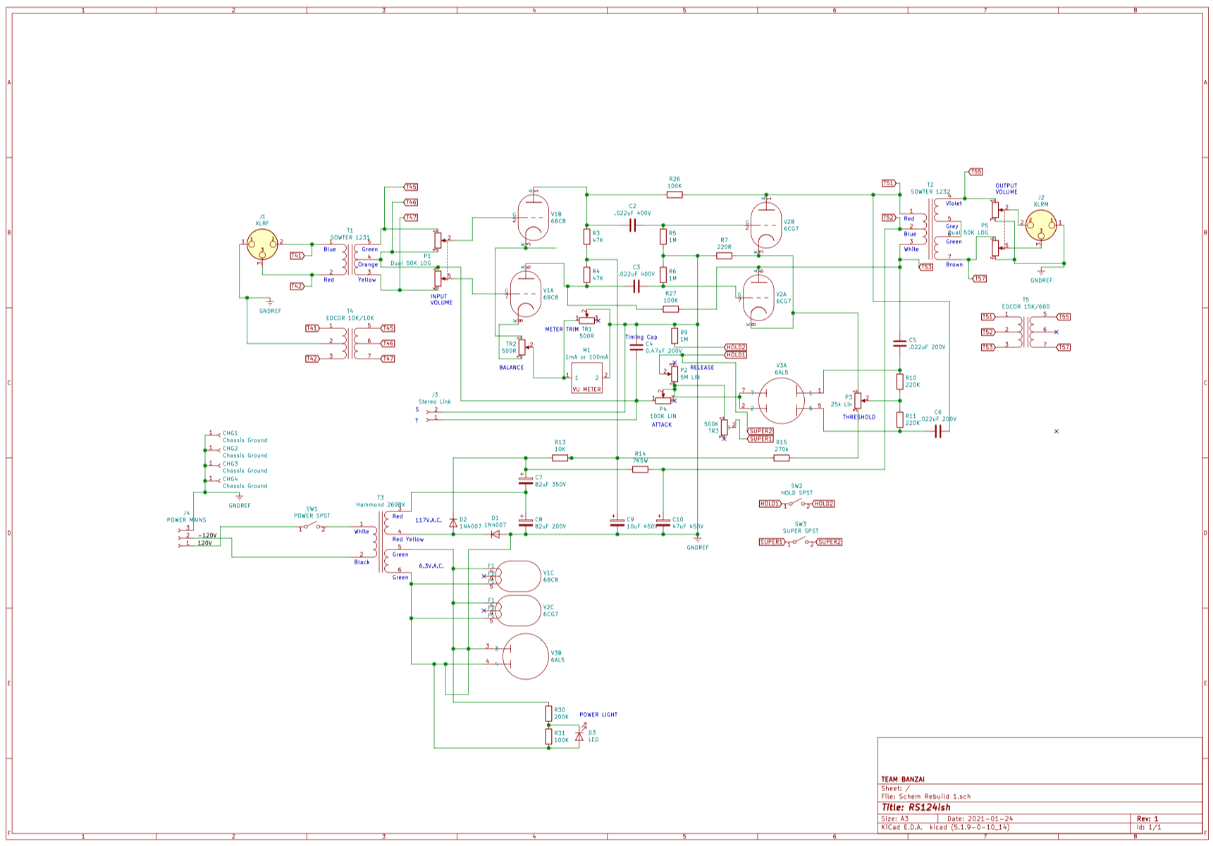
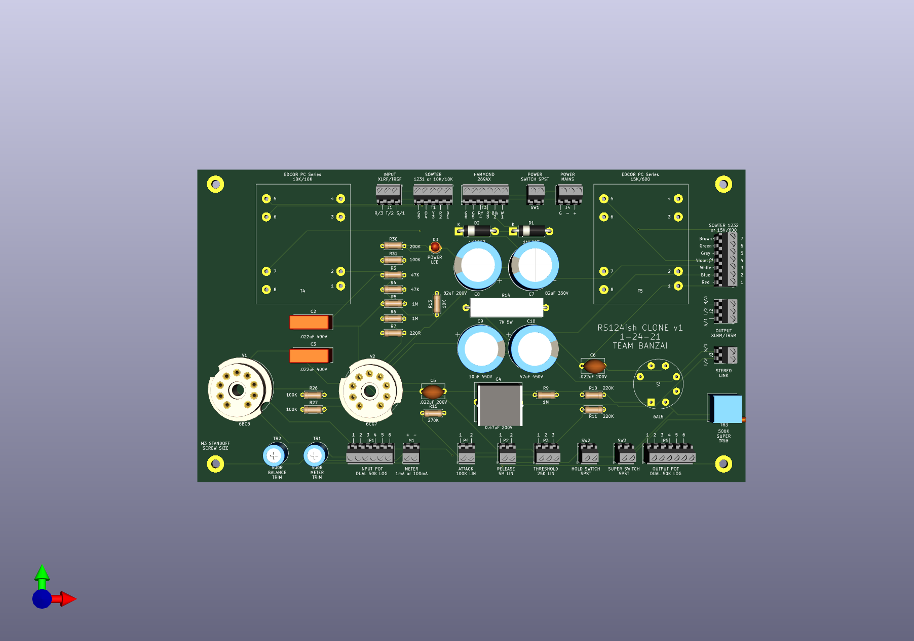
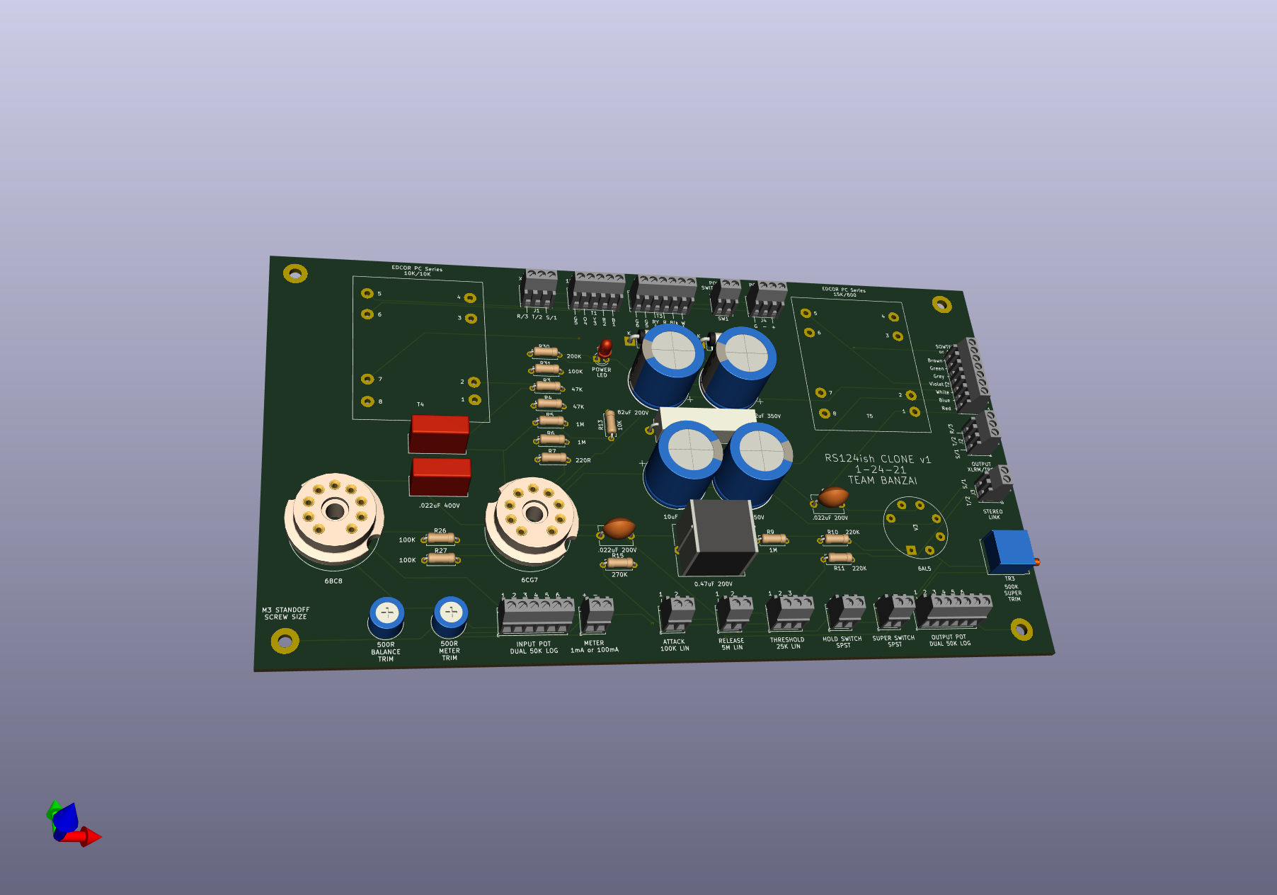
Hello all. I have been lurking here for a bit, and finally have had some time to work on a bucket list project of an RS124 clone that can easily be implemented into stereo builds. Here is the current schematic based on the one Winston O'Boogie posted, and a 3D PCB Mockup. Part of the plan is to have the BOM printed entirely on the PCB for ease of use. Pretty sure how it is set up currently one would be able to use the original attack/release switches as well as implement the original output attenuator.

dxXawyd.png

k6ohF5I.png

NWrkHcM.png


Changes Implemented:

- Adjusted some cap values to closest easily available
- Added Power LED instead of lamp
- Input and Output Pots are now 50K Dual Logs, will probably implement the shorting pin 2/3 method listed above
- Attack is a 100K Linear Pot
- Release is a 5M Linear Pot
- Hold switch is a standalone switch for whatever the release was left at (see question about this)
- “Superfuse” mode is a 500K trimmer resistor and switch in parallel with the release (see question below)
- Input/Output designed for use with original transformers, Sowter transformers, and Edcor PC series.

Possible additions:

- True Bypass
- Original Power Lamp wire terminal


Questions for the community:

- Hold Circuit: I think I have implemented it correctly in the schematic by converting it to a switch that kills the release pot to the cap. If someone could confirm this that would be awesome.

- Superfuse: With my understanding of how it works from this thread: https://groupdiy.com/index.php?topic=68787.0 , from what valveandsound said, I think I implemented the 500k trimmer resistor correctly in the schematic. If this could be confirmed that would also be very awesome.

- I did my best to try to recreate the original schematic of the altec + the emi RS124 (minus the attack release switches) so that it was a bit easier for me to understand. I may have mucked up parts so having another set of eyes on it would be helpful.

- If someone has a bit more clear schematic/explanation of the original pot switch wiring I can add it to this schematic for reference when building.


Cheers!
 
jazzcrisis said:
I built a souped-up stereo RS-124 recently that I think comes close to a Fairchild's capabilities. It's definitely as fast, but does sound a little different. It's essentially a stock RS-124 circuit with the following additions:

1. (2) 6BC8 in parallel per channel. (still requires careful matching, but makes it much less sensitive to tube variations)
2. Regulated B+
3. Cathode Follower feeding the sidechain.
4. True stereo sidechain.
5. Sidechain HPF.

It's a monster, and I can get it faster than I'd ever need it without any hint of thumping or motorboating. Very, very good master bus compressor.

Hi jazzcrisis, are you willing to post the schematic of your modifications? Sounds very interesting. Cheers
 
teambanzai said:
Yet Another RS124-ish Clone PCB Project

Hello all. I have been lurking here for a bit, and finally have had some time to work on a bucket list project of an RS124 clone that can easily be implemented into stereo builds. Here is the current schematic based on the one Winston O'Boogie posted, and a 3D PCB Mockup. Part of the plan is to have the BOM printed entirely on the PCB for ease of use. Pretty sure how it is set up currently one would be able to use the original attack/release switches as well as implement the original output attenuator.

Hi, the PCB looks great. I built this compressor a while ago and use it for every(!) work I do. Its simply a great sounding device. So easy and amazing. However. I like your approach of implementing everything on the pcb with easily available components. I am wondering if the trace width and spacing is already finalized. Because the traces appear really thin. Especially those for mains and HV.  I can not comment on spacing and clearance but for my humble knowledge of PCB design this is definitely to be considered. Excuse me if I am wrong. My question only arises from my visual impression of this sweet 3d graphic.

Best,
Falk
 
Falk said:
Hi, the PCB looks great. I built this compressor a while ago and use it for every(!) work I do. Its simply a great sounding device. So easy and amazing. However. I like your approach of implementing everything on the pcb with easily available components. I am wondering if the trace width and spacing is already finalized. Because the traces appear really thin. Especially those for mains and HV.  I can not comment on spacing and clearance but for my humble knowledge of PCB design this is definitely to be considered. Excuse me if I am wrong. My question only arises from my visual impression of this sweet 3d graphic.

Best,
Falk

Rad! I own a Chandler RS-124 and use it on almost all my projects at work. Have always wanted a more mastering oriented version that wont break the bank  ;D
The PCB is not final at all! I should have mentioned that in my post. 8) It is in the very very early stages, I just like designing the PCB as I go along figuring out the schematic. I am more of a technician and a visual learner than a traditional E-engineer so its how I am fully learning how this thing works. I just have kicad autoroute stuff for temporary visuals so not to be staring at rats nests the entire time. I will do much thicker traces and ground fills when the layout is closer to done, and do more exact footprints on some of the components. Very glad you like the idea of being able to easily switch out options and have everything placed on the board with minimal floating parts.

I would love to add the mods described by Jazzcrisis to the project, all with the options to make it "stock" or to have it be a modded beast.
 
The pictures are a little big to be able to view them as a whole on my device but...

A few things that jump out:

To keep hum down you'll need to ground the centre-tap of your heater winding rather than let it just float.  Elevating an AC heater supply by about 25 volts with respect to cathode can help further if needed.  Do that with a divider from the clean H.T. and the  cap bypassed 25V injected at the 6V3 AC C.T.

Looking at the specs of your specified Hammond power transformer (269BX), the HV winding isn't 117VAC but 300C C.T.,  so copying the original Altec voltage doubler will be a no-no.
If you already have that transformer then use a full wave bridge across the whole winding and plan on losing over 150V DC in wasted heat with larger series resistors in the filter banks.
However, if you can, buy the Hammond 269AX instead  with 250V AC C.T.  and you won't need to lose so much DC voltage. 

The dual pot at the input is supposed to be sized to appropriately terminate the input transformer so I wouldn't assume a dual 50K is correct for all input types. 
On a particular transformer I used, a dual 25K  was more appropriate.  Just giving a heads up here, not pointing out an error. 


However, a dual 50K is WAY too high a value for the output - in terms of load on the output transformer, but more importantly in terms of presenting a high source impedance to the outside world at most settings. 
The simplest output level control would be a single 1K log and would be a decent all round load for the output transformer and be a low source impedance (approx 250r at worst case) to send down the cable.

I don't know what the ratio is of the Sowter output transformer but, last I looked, the ratio they were specifying for an Altec was higher than original.
You're ideally looking for about a 7:1 turns/voltage ratio.  So a 30K:600.  Others have used slightly lower ratios so there is a little leeway.  But 7:1 was what worked for me.

The meter wouldn't generally be your lower specified  1mA, never mind a 100mA.
Just use a decent VU meter with the internal diode rectifier removed.

When laying out your actual PCB, use the same good practices you would if it were a point-to-point layout.  This has been posted before, but Merlin's page here:

http://www.valvewizard.co.uk/Grounding.html

is a good guide to follow.  Not only in terms of grounding, but with respect to keeping  the current of each stage tightly contained within its own small loop.  Doesn't matter if it's point-to-point or a pcb, the same rules apply.


Latest posts

Back
Top