1073 1084 with EQ DIY project HELP THREAD

GroupDIY Audio Forum

Help Support GroupDIY Audio Forum:

This site may earn a commission from merchant affiliate links, including eBay, Amazon, and others.
Would be cool to have a partslist. At least for the two amp boards.

I'm kinda stuck in stuffing the parts into their right place.

Filter boards are easily stuffed.
 
Yeah, the parts are clearly labled on the boards. I'm not really concerned about caps and resistors, it's all the other items I'm not so certain about. I just emailed audiomaintenance asking about inductors and tranny's (power too) If they have some specific part info, of course I will post what I know here for everyone.

I guess I should inquire about any specific cap locations that are "critical" and need to be of a specific type of cap? I see a discussion in another thread about caps and audio and most of the information seems to based highly on opinion instead any facts. Good, bad, or indifferent I think I'd rather go with the more "tonal" varieties just to see.
 
Hey Josh, I have my 2x 1073's all "stuffed" and ready to go.
I went with "what I have" for some things, but used the "Orange drops" in
the BA205 and BA211, along with large Poly caps all in the 250v-1000v range. ( this was just a "size" thing.
These were all good quality either Vishay or Wima / MKT types
Tantalums for the BA284/283 where 10u/22u 16&25v are placed near the
edge connector.
Went with 100uf in the 64uf & 80uf slots and pf values are a mixture of
ceramic/poly and polystyrene.
I got my inductor sets from Max's group buy and have devised a small
stripboard that will convert them to fit these cards, I'll post them up when I
get to it !
Just got to save up for those 6x transformers .... ouch expensive !! and also
wait on the dual concentric ideas.
As for the case .... need a 2u solution that looks good, perhaps I'll go with
a FPE front panel.
I think this will be a few months away from completion

Marty.
 
This is a good resource to start with:
http://www.groupdiy.com/index.php?topic=4754&postdays=0&postorder=asc&start=0

because you find this:

http://www.linear-recording.com.au/Graphic%20Design/Photos/1073/1073.xls
maybe not to follow strictly, but a good comparing tool.

I'm going with a 3units chassie (I have a lot of room in my rack...)
 
:shock: WARNING WARNING WARNING WARNING WARNING !!!!!!!!!!!!!!!!!!
There s a "big" mistake in the b283AV which escape to my eyes when doing the gerbers (and to kubi maxwall and codered too)

left colector hole of 2n3055 is included in the trace going to pin F.
this shunt C7 (80uf btw use a 100 uf here)!!!!!!!
soluces : with a dremel or a knife etc cut a circle around the pad hole trace.
OR if you don t have a rotative instrument USE a nylon or teflon screw only for this pad hole so you isolate the 2n3055 body (the colector) from this trace.
BUT use a metal screw for the B trace.
I will borrow a camera tomorow and post a pic....
Now you can blame me :oops: :oops: :oops:
you can throw to my face everything you have near you.
i prefer lo1166 valves solen caps etc.....
audioforge
 
######What, no, never!!

i cant believe it!!

might have to sell my cards, or just go ahead and make them, with your help.

thanks for the heads up

Iain
 
yes ! after posting last night the first error i realize i fucked the 2n3055 footprint :oops: none of the final checkers saw this BUT I am the final one to blame. this is a "beginner " fault but i have NO excuse for that.
i must confess i didn t sleep well last night.....
here the soluce with pics.

For thoses who will be afraid to do it .email me first and sent back your b283 boards .i will do the mods and sent them back to you free of charge.
doing a new 283 batch will cost me with shipping to you around 1150 euros.
as it was a non profit project i can t do it. but i will take the shipping back from my money.
here the pics.
you need a cutter a nose plier.... dremel if you have ....
first peel carrefully the varnish where indicated to solder resistors tails.
and cut the trace around the 2n3055 emiter and base pad holes.
do it carrefully to not cut the C trace totally!!!!! see the pic.
control with a voltmeter the trace continuity and that you have correctly isolate the 2n3055 emiter and base from the traces pin C and D.
for the 2n3055 screw hole (trace F). use a 3mm diameter nylon screw or cut enought arond the pad hole so your head screw is isolated from the F trace. control with your voltmeter.
b283avmod1c.jpg


b283avmod2b.jpg


b283avmod3b.jpg


wrap a resistor tail around the emiter and base of the 2n3055 pins.
adjust the reistor tail lenght to the copper trace you have created when you peeled the varnish. solder...
your board is now functionnal....

audioforge
 
Pierre,

Possible to do a new run of B283AV boards instead of repair , I won't mind paying for it , it can't be that much ? right.

I'll order 4 of them if you decide to run a new batch.
 
the ba 283 seems a good utility for other projects so a new batch
grp buy may not be a bad idea .

I won't get to the 1084 for a while , hope there's no other Oops in there
I guess that's what makes proto typing not so expensive in the long run .

Sorry it happened ,
 
Here's my fix's to the two boards I have :


93834916.jpg


93834934.jpg


First one I cut the trace completely !!
Had to use wire to make it good, the second one was a new 3055 with quite
long pins so I used those for the new connection.
It can be done, be careful and it makes a mess of the boards - which is a
shame.
Continuity test is all good.
Marty.
 
Before everyone goes Dremel crazy here are a couple of other ideas.

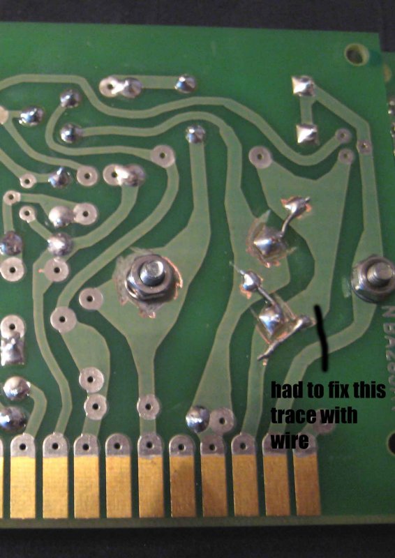
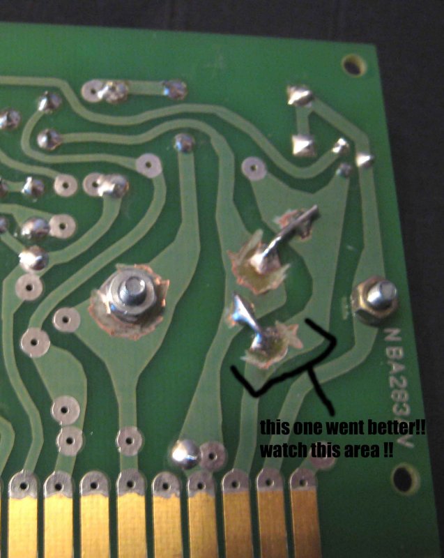
@Pierre: don't feel too bad - I've fixed enough 'professional' boards with far worse kludges than this - and in some quite 'name' gear too.

Worst mirror image problem was in a batch of boards I had to rework for a local disco light company: they'd mirrored the TRIACs ....... the first tests of boards were spectacular to say the least, until they spotted the problem, (for the non electronics people I might explain that a TRIAC is used to switch mains power to the lights, mirroring a package puts the mains on the control terminal - and they explode, literally!).

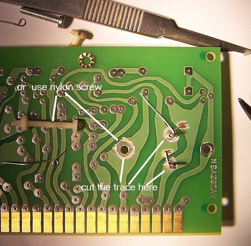
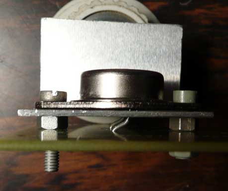
First idea: Don't lower the floor, raise the ceiling. Not a new trick, but easy if your heatsink isn't too thick. I just knocked up the bit of alloy to make the trick show more easily - this is not my actual heatsink. A bit of PTFE sleeving over the pins would be good. I've used a nylon bolt for the faulty hole. Relatively easy, and no board modding, (and possibly better air flow).

2314832887_6f0ab2c51b_o.jpg


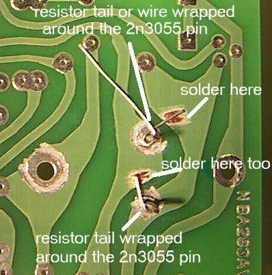
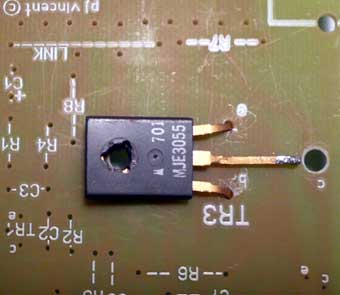
Second idea - go lateral. use an MJE3055 of TIP3055. You'll nee to fab up a different fin, and use a nylon bolt again. I haven't extended the centre (collector), lead - it needs to be slightly extended down the original hole. A later check shows that some 'flat pack' heatsinks will fit without modification. the taller twisted fin type should be OK.

[EDIT] I've just pulled some various 'flat pack 3055' data sheets. You'll have to watch the pin outs - some are (L->R) BCE others ECB. Both can be made to fit - just that, obviously, there is a need to check.

2315642974_acc385fac9_o.jpg


By the way: before for any authenticity fetishist says "it's not a 3055", I might point out that 60% of what is labelled 3055 isn't either, unless you buy from a major company. Most 3055's are regarded as 'generic NPN power' and sourced from production drop outs of higher rated devices. The flat pack ones at least come from a major maker, and will have the correct semiconductor die inside the package. At this power level, heat transfer is not going to be an issue, (the flat pack ones have a slightly lower max power dissipation).

[EDIT] Doing some 3055 checking reveals that quite a few bigger makes may be 'selects' too. One Motorola data sheet quoted Ft anywhere from 0.6 MHz to 6MHz. Typical should be 2MHz, looking back at an old original RCA data book. Flat pack 3055's all seem to have a lower max current of around 10A, as opposed to 15 in the T03, (due to package limitations). Not really relevant here - the die is theoretically the same.

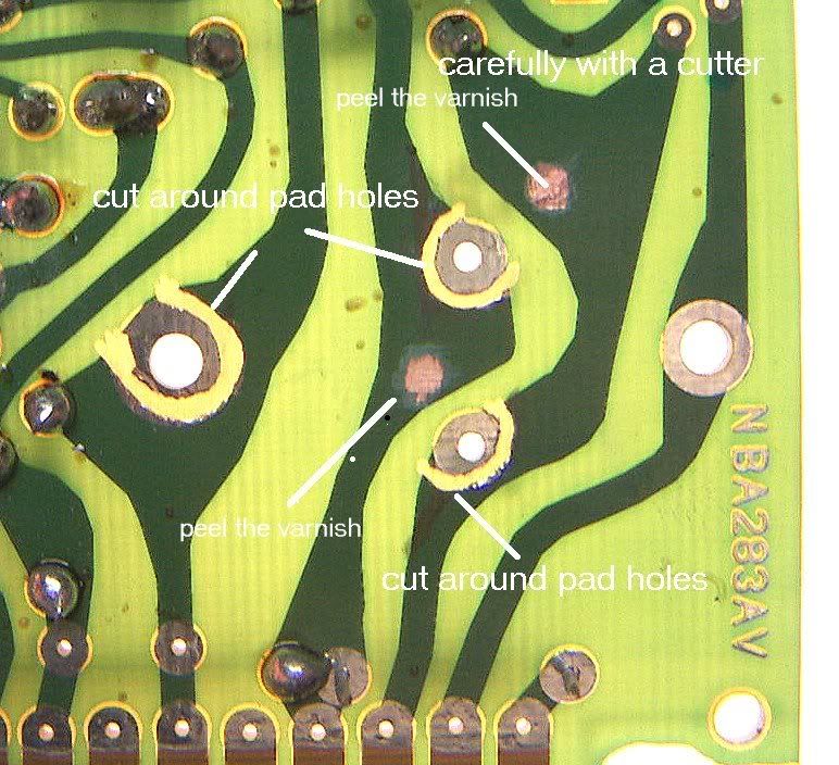
I think the flying heat sink method is the easiest. A Hint: when bending the pins, hold the pin next to the case with your needle nosed pliers to avoid cracking the seal. Another option is to solder some wire on to go down the holes and trim the pins to clear the board.
 
if you decide to reman this board, i will take 4 PLUS shipping. when your doing this for a living i will cmplain, untill then THANK YOU FOR YOUR HARD WORK!!!

Oh, and Mike, think im gonna be mithering you for some help.... :oops:

Iain
 
Excellent solution, Mike.

you always have to think in three dimensions all the time.
sometimes the simplest solutions are just right in front of you, and go
unrecognized so easily.
 

Latest posts

Back
Top