1975 Allen & Heath MOD2 Rebuild Project

GroupDIY Audio Forum

Help Support GroupDIY Audio Forum:

This site may earn a commission from merchant affiliate links, including eBay, Amazon, and others.
Got the power/monitor amp channel re-capped! Woohoo, time to fire this baby on and start working on the channels!

IMG_0074.jpg


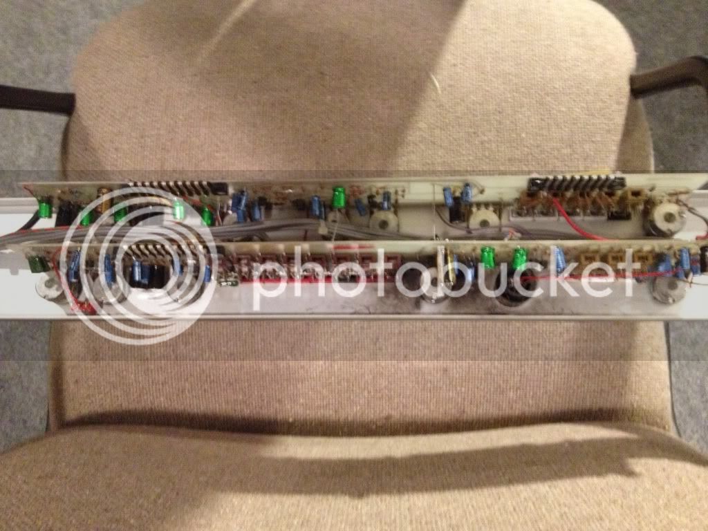
New pictures in my photobucket page for those who are curious! Check page one.
 
I have a MOD 2 as well & have the User Guide WITH circit diagrammes if you want them send me your email address & I will scan & make an adobe acrobat file (PDF) & send it to you.

The MOD2 uses a +24v PSU you can build one quite easily I have replaced all the meter lights on my meter bridge with 12v lights out of a car!  2 12v light bulbs add up to 24v psu & they are quite good with thw meters!

sorry about the spelling Im Dyslecic & Autistic so I have dificalt with reading & writing!

Let me know if you need more help Im an electronic engineer & sound engineer, I will help if I can!


Guy Greenwood
 
meter lights... wow I'd like those.  can you tell me how to make the connections?  I would assume that they simply connect to the 3 prong power plug on the master module.  can you let me know?  the meters on mine are Modutec.
 
The documentation that I have for my Allen & Heath MOD2 mixer states that the console should be provided with a 21 volt supply with a negative 0 (I am assuming this means -24 volts). 

I measured my power supply output at +24.7 volts today. 

I've read somewhere that the amp transistors (BC168 and BC169) can react positively to a slightly higher voltage.  My question is: should I adjust the supply to exactly 21 volts or leave it at the 24.7 voltage? 

I also noticed that the rails are not connected to the sensing terminals on the power supply. Can someone please help me determine if the sensing should be used?  Should these terminals be strapped together?

 
musika said:
The documentation that I have for my Allen & Heath MOD2 mixer states that the console should be provided with a 21 volt supply with a negative 0 (I am assuming this means -24 volts).
 
no, '0' = 0, it uses a single supply PSU. If you have a +24V/0V/-24V symmetrical PSU, just connect +24V & 0V, do not connect the -24V.

I measured my power supply output at +24.7 volts today. 
I've read somewhere that the amp transistors (BC168 and BC169) can react positively to a slightly higher voltage.  My question is: should I adjust the supply to exactly 21 volts or leave it at the 24.7 voltage? 
Your desk will likely run on 24.7V well, but it will produce more heat. Personally I would adjust to 21V, so you are able to check reference voltages in the diagrams.

I also noticed that the rails are not connected to the sensing terminals on the power supply. Can someone please help me determine if the sensing should be used?  Should these terminals be strapped together?
I would connect the sensing terminals to the output of the PSU and suggest to use a 'thick' power-cable to connect to the console.

grT
 
Thanks for the advice... greatly appreciated.

I also replaced the power cord with a three wire heavier power cable (to the 110V from the power supply).  Should I also connect the ground to the power supply?  It formerly had a 2 wire cable.  I'm not sure where this console is grounded to in the structure?  This has always been a mystery to me since I've never really disassembled the plug in panel of the console.

Can you help me out with this grounding question?

btw I have finished recapping all the input and output modules (finally)!!!  This job seemed to last forever, but now it is completed and I'm anxious to get the power supply issues solved.

 
musika said:
I also replaced the power cord with a three wire heavier power cable (to the 110V from the power supply).  Should I also connect the ground to the power supply?  It formerly had a 2 wire cable.  I'm not sure where this console is grounded to in the structure?  This has always been a mystery to me since I've never really disassembled the plug in panel of the console.
Can you help me out with this grounding question?
From a safety perspective the casing of your power-supply must be grounded.
It is in most cases also best to have the console be the 'star-point' in your grounding system.
Please check/measure if the '0V' is connected to the casing/module frames of the console (it should).
You then have to decide where to connect the '0V' to the ground connection, likely most practical is to do this in the power-supply at the same point where you attach the ground to the chassis.
Maybe you can post some pictures of your PSU so we can have a look.

grT
 
OK.  I'll post some photos of the console and the power supply later today.

I did as you suggested and connected the sensing to the -0 and +24 terminals and adjusted to +21V.  This power supply is a single 24V generic supply.

The 48V power supply which I have removed for now was a dual output and was connected +48v and -48V. I don't think that was correct! 

If I am correct, in order to physically see where the console is grounded to the metal case (with the female McMurdo connectors attached) one would need to remove the side panels in order to do so. Remove the left most input channel and the right most output channel and I think you will see what I mean.  This is why I say it is a mystery to me concerning the console grounding.

David
 

Attachments

  • Allen Heath 21V 3A Power Supply.jpg
    Allen Heath 21V 3A Power Supply.jpg
    61.9 KB · Views: 11
Hi All,

I'm waiting on a new rotary spring loaded power switch for the MOD2 power supply (pictures included).

Also, I would like to hear comments on how to update the grounding system and wiring in general from the underside of the console (see pics).

Sorry it took much longer than I thought to flip the console so that I could actually see the wiring.  I have made some comments on the photos too.

http://www.flickr.com/photos/76115376@N08/

David
 

Attachments

  • PS Front Panel.jpg
    PS Front Panel.jpg
    271.1 KB · Views: 7
Grounding using the Star scheme.

Does this mean that each input and output channel strip plus the master monitor modules will be wired to the copper blocks that I'm going to mount on the back side of the console?  I'm thinking of running a 16 or 18 gauge stranded silver wire to the star blocks which will be connected via 10 gauge wire and then from the star a heavy wire directly to the power supply ground and then also a heavy ground wire to the building earth (water pipe).

 
Pleasantly surprised to find some discussion happening about this old A&H console.
On my way home the other day I came upon a MOD 3 dumped rather unceremoniously in the street. I maneuvered the thing back to my house and pulled it apart - all original including caps, minus a psu and a knob or two but that's ok.
Seeing as I was planning on buying a whole bunch of P&G faders etc anyway for a summing mixer build, I think I will direct my efforts toward restoring this old desk instead and pick up the eq's and metering. Time to get out of these DIY diapers and get me a scope and an education!


Attachments

  • IMG_3820.JPG
    IMG_3820.JPG
    50.1 KB · Views: 63
I uncovered a 4 resistor circuit on the underside of the MOD2 which uses 100 ohm values.  It is placed between the 21V power rail and the 12V power rail that is used in the output modules for their relays.  I'm not sure what purpose it serves.  Can anyone help me?
 

Attachments

  • 100R Buffer.pdf
    18.5 KB · Views: 22
Where exactly are the resistors, do you mean on the underside of the steel bus extrusion? Or on the master module card(s)?

edit: sorry - I think you are saying they are on the output modules, is this correct?
 
Looks like a parallel/series voltage dropper for the relays. This arrangement would give 100R total resistance. I would expect to see a filter cap at the relay end, as well as spark killers on the relay coils.

 
...this resistor arrangement is located underneath the buss connectors (steel extrusion panel - system ground). 

On the master module there is another 100 ohm 1 watt resistor connected to the output relay buss.

As far as the filter cap and spark killers, I'm not sure I see them on the drawings.

Towards the end of the Flikr photos there are pics of the underside showing this voltage dropper.

  http://www.flickr.com/photos/76115376@N08/
 

Attachments

  • AH MOD2 Output Modules.pdf
    242.8 KB · Views: 16
No, maybe the caps were not necessary. They would prevent relay switching clicks from making it back onto the audio supply. If the relay current is low and the audio supply is laid out well enough it may not need the extra help. This is definitely the relay dropper though. A single 1w 100R should make a neater replacement if you feel like tidying up.

 
Thanks Dan,

So, it seems like all that is needed is the 1W 100R and I should be able to pull out the 4 resistors underneath replaced by a wire connection.  I did do the math just for my own learning experience.

David
 
Wait, I missed this bit -

musika said:
On the master module there is another 100 ohm 1 watt resistor connected to the output relay buss.

Now I'm not so sure what this other arrangement on the module connectors is. I suspect a mod - possibly a PFL relay mod or something similar?

Perhaps try lifting one end of the resistor chain and see what happens?

It doesn't usually do to just replace resistors with plain wire.  :)

 
I seem to remember reading something about an upgrade to the output modules now that you are mentioning this and it may be that my console has this mod... it was a paper put out by A&H.  I'll look for it. 
 
Back
Top