6AQ5 program amps

GroupDIY Audio Forum

Help Support GroupDIY Audio Forum:

This site may earn a commission from merchant affiliate links, including eBay, Amazon, and others.

Conviction

Well-known member
Joined
Mar 27, 2013
Messages
318
Location
Sweden
Hi everyone,

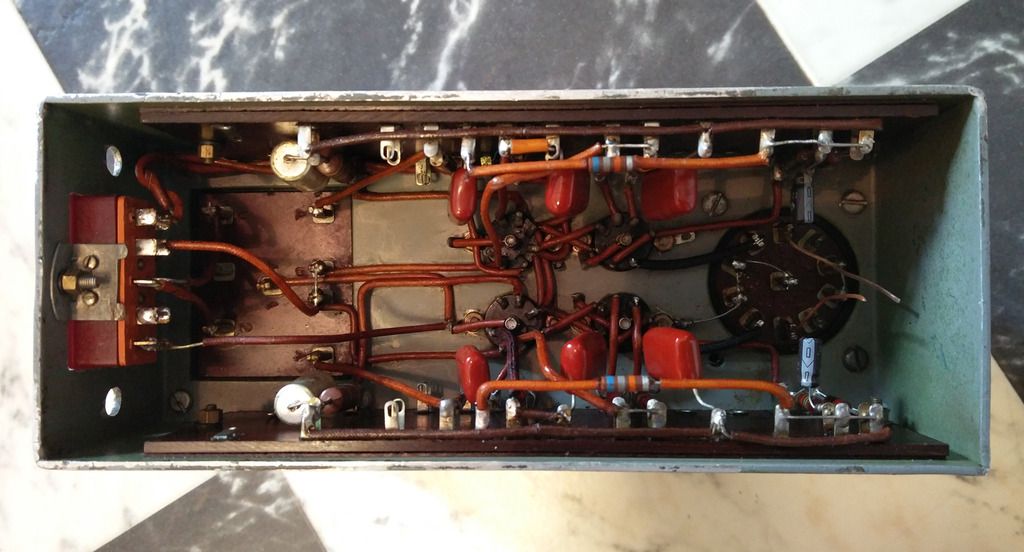
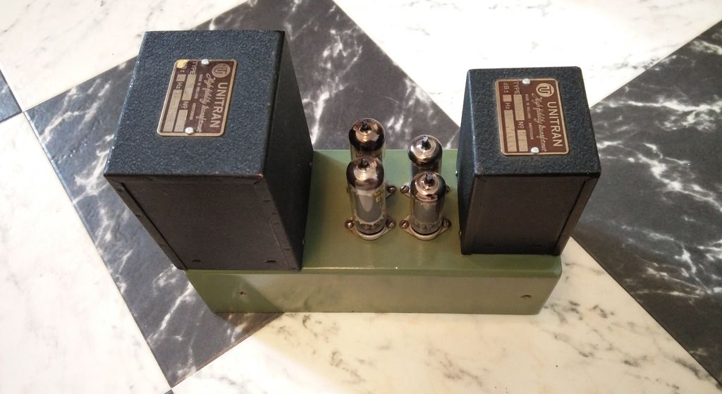
I've got a couple of presumably-Philips 6AQ5 program amps with Unitran in and output transformers. Thing is, all they do is distort when I feed them more than 20 volts B+.

Attached is a rather quickly drawn schematic showing one half of the amplifier. They're fully symmetric, Williamson style.

I assume plate voltage would have been something in the range of 200-250VDC (as per data sheet).

Where would you begin?
Could it be something related to the feedback? I'm out of luck here.

Best regards,
Olle
 

Attachments

  • 6AQ5_6AU6_PHILIPS_PGM_AMP.jpg
    6AQ5_6AU6_PHILIPS_PGM_AMP.jpg
    150.5 KB
They need a lot more than 20v B+-; more like 300V. Try running them at 300V and measure the cathode current by measuring the dc voltage across the cathode resistors.

Cheers

Ian
 
So measure the DC volts at all key pins, see why it is sick.

BTW: 37K is a very unlikely value the two places it appears.
 
ruffrecords said:
They need a lot more than 20v B+-; more like 300V. Try running them at 300V and measure the cathode current by measuring the dc voltage across the cathode resistors.

Cheers

Ian

Thanks Ian!

Of course they need a lot more! The thing is that I've got quite the output at 20 volts, which puzzles me.
Initially I thought these were meant for speaker output, but the output transformer secondary reads 31 ohms DCR (which should equal a line winding, right?)

With B+ at 250VDC I've got 15.8 volts (on both halves) across  the cathode.
6AU6 cathodes stays at 1.79 volts.

Thanks!
/Olle
 
PRR said:
So measure the DC volts at all key pins, see why it is sick.

BTW: 37K is a very unlikely value the two places it appears.

I have no idea where 37K came from  :eek:
They're actually 470K. Would that be in order?
 
emrr said:
Is that first stage cathode bypass cap in the right place?

Hey Doug! I just measured the voltage across the 6AU6 cathodes: 1.79 volts on both.
I think I might have drawn the polarity wrong in the schematic, if that's what you're referring to.  :-X
Sloppy work.
 
It's normal to get healthy output at minimal voltage, with lesser gain change as voltage goes up exponentially.  Makes sense it would distort easily at that B+. 

Cathode bypass:  I'm not imagining that NFB path is doing much of anything with that cathode voltage divider and a bypass cap where it is. 
 
> Is that first stage cathode bypass cap in the right place?

I don't see a problem. A similar thing on the Fender AA Champ. 1.5K for DC bias, bypassed. 27K:47 divider from output, the voltage on the 47r injected below the 1.5K+22uFd. The first stage gives full gain. If the divider values were raised so to use 1.5K unbypassed as the lower leg, that stage gain would be about half. The total NFB stays around the same but more works against the output stage's errors.

> 6AU6 cathodes stays at 1.79 volts.

Did ask "all" pins. A drifty G1 or plate or screen resistor could spoil things. Symmetry may not be good after 50 years.

1.79V in 1510 Ohms is 1.18mA cathode current. Assume 25% screen split, 0.89mA plate current. In 220K this is a 195V drop. 195V down on a 250V B+ is an awful low plate voltage, 55V. Not wrong, but curious.

> 15.8 volts (on both halves) across  the cathode.

6AQ5 does not come in halves. This is one 470r with both tubes flowing??

15.8V/470r is 33.6mA cathode current. Near 8 Watts total heat in *two* 12W tubes. Won't melt! BUT this looks like the right value for ONE 6V6/6AQ5, not two. If you have a dud, that would be bad waveform. Since dissipation is far below rating, you can run it with one 6AQ5 at a time, see which one is lazy/dead. If you have two 470r, one each tube, then 15.8V is spot-on within usual tube tolerance.
 
> Cathode bypass:  I'm not imagining that NFB path is doing much of anything with that cathode voltage divider and a bypass cap where it is.

I accept the topology. However the values seem wrong. (Send it back to the guy who wrote "37K".)

68K to 22R suggests they want to NFB-limit the gain to 3,090, K1 to P2. Take 6AU6 gain as 100+, 6AQ5 gain as 10+. That's over a thousand, but not much over 3000. Being generous, 6AU6 = 250, 6AQ5 = 15, 3,700. That's not effective NFB. And forward gain of 3,000 between transformers is a LOT.

I might look again to see if it is 220r. (6.8K seems unlikely, as it would steal about all the power a 6AQ5 makes, load-down, also get-hot, also throw a bass-rise at 250Hz.)
 
Conviction said:
Thanks Ian!

Of course they need a lot more! The thing is that I've got quite the output at 20 volts, which puzzles me.
Initially I thought these were meant for speaker output, but the output transformer secondary reads 31 ohms DCR (which should equal a line winding, right?)
Thanks!
/Olle

Yes these are definitely line level output devices.

Cheers

Ian
 
PRR said:
I accept the topology. However the values seem wrong. (Send it back to the guy who wrote "37K".)

They're 470K! I have no idea how 37K got in the schematic.

I might look again to see if it is 220r. (6.8K seems unlikely, as it would steal about all the power a 6AQ5 makes, load-down, also get-hot, also throw a bass-rise at 250Hz.)

It really is 22 ohms!

6AQ5 does not come in halves. This is one 470r with both tubes flowing??

Sorry, was a little too quick there. Halves=both halves of the amplifier.

I'll measure everything later today. It would be really nice to get these working. UNITRAN transformers seems to be the holy grail among audiophiles. Some of their outputs got impressive specs. How about 10-80000 within +/- 1dB? Then again, one could question the reason behind this (too bad we can't ask Williamson). This is way beyond my current (!) knowledge.
 
IMG_20160805_130122_zpsrqw6z0tz.jpg


IMG_20160805_130046_zpsuvdu1w2r.jpg
 
Back
Top