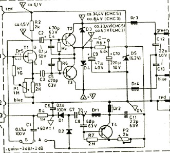
A Direct-Coupled Input-Capacitorless Active Preamp deleted

GroupDIY Audio Forum

Help Support GroupDIY Audio Forum:

This site may earn a commission from merchant affiliate links, including eBay, Amazon, and others.
I've been looking at this thread on and off and obliquely, partly because I was thinking along somewhat similar lines before it began and didn't want to have cross-influences as yet.

But I want to mention Funasaka and Kondou, Feedforward Floating Power Supply, JAES vol. 30, No. 5, 1982 May. I missed this paper and developed a similar approach, and after publicizing it in 1997 had this prior work brought to my attention.

The essence is to pick off the input signal and drive the rails, rather than bootstrap them to the output, thus avoiding the delays. It's still a tricky job.
 
[quote author="bcarso"]I've been looking at this thread on and off and obliquely, partly because I was thinking along somewhat similar lines before it began and didn't want to have cross-influences as yet.

But I want mention Funasaka and Kondou, Feedforward Floating Power Supply, JAES vol. 30, No. 5, 1982 May. I missed this paper and developed a similar approach, and after publicizing it in 1997 had this prior work brought to my attention.

The essence is to pick off the input signal and drive the rails, rather than bootstrap them to the output, thus avoiding the delays. It's still a tricky job.[/quote]


For the subject mic preamps the nominal DC input level should be reasonably slow moving once stabilized. The flying PS will typically be sized such that it doesn’t need to move to accommodate audio signal and handling CM inputs will be similar to ground based cap coupled designs.

There may be some new issues related to protecting devices for transition between phantom on/off this too is somewhat similar to cap coupled designs.

Tracking power rails are used in a handful of modern power amps used in sound reinforcement. This provides improved efficiency with audio quality similar to classic class A/B topologies. Of course the average or continuous power will now be PS limited but peak to average can be better matched to music’s dynamic range. One popular amp only guarantees full 2 ohm power for 20 mSec, others are more generous.

I dabbled in a trick high peak to average (120W/35W) power amp in late ‘80s and recall difficulty with both providing adequate PS lead for clean transient response while keeping edge rates down to minimize PSR issues. I abandoned the approach for higher power points as the economics of my particular approach didn’t scale well. The modern approach using switchers for the tracking rails looks pretty promising.

JR
 
[quote author="mediatechnology"]

Brad - Do you have that cite?

[/quote]

I have a photocopy that surfaced recently which I could scan for you---send me a PM with an address. Quality will not be great but maybe adequate.
 
[quote author="mediatechnology"]Thanks to everyone who sent me the JAES Feedforward Floating Power Supply cite. I don't feel right about linking directly to the pdf on this one but I think figure 7, below, is not a significant "taking" of the work. If anyone objects to it being here I pull it down. But for now:

And if I'm feeling really bad and receive enough encoragement from the people who sent it to me I'll host the whole thing. Is it available online? Would I be diminishing the value of the original?

Now isn't this interesting. This circuit provides some wonderful slew rate improvements to a common op amp. They made a 4558, yes a 4558, slew at 300 v/uS. We could still use this trick. And perhaps we do...

Topologically speaking, it's very similar to the DC-Coupled preamp. Kudos to Brad for seeing the similarity. The big difference is well, speed and motivation.

Think of the op amp as the 1510. The FFPS block in my gizmo is a big, slow, integrator. Add a "big" C at the gate of Q1 and you're there. Now in my case Q1, Q4 and Q5 are an op amp. The emitters of Q2 and Q3 drive the "HV" op amp and become "flying rail drivers" for the whole contraption.

Now isn't this cool. We use a bootstrapped op amp to get HV operation from a 1974 cite in EDN and a 1982 circuit in JAES to fly some rails around.[/quote]

From inspection yes it will slew at a rate limited by the discrete follower circuitry, but the ability of the opamp to slew relative to that and correct for any non-linearity in that PS circuitry while driving a load will still be limited by it's normal static rail slew and GBW capability. I wouldn't get my hopes up for this leading to a super HV opamp based on 4558 guts. While it should do respectably well with a modern high performance opamp.

FWIW the symmetry of +/- rails will vary with JFET Vg-s for the given operating current.

JR
 
[quote author="mediatechnology"]As you know John I'm not using it that way. I'll send you the cite for a reality check.

But they do support their claims with measurements. One 4558 plot with FFPS shows a 100 KHz 10 Vrms distortion level of 0.005%. RL was 10K ohms. The rail voltages were +/-50V. The 4558 plot without FFPS at that distortion level was 20KHz at 1Vrms. The bare 4558 wouldn't reach 10 Vrms at any frequency. With FFPS at 20 Vrms (again RL at 10K) it could produce 50 KHz at 0.0025%.

But it may be "Bravo Sierra" or the real circuit they used wasn't figure 7.

Point is there's precedent for feed-forward rail flying.

Thanks again bcarso et al for sending me the cite.[/quote]

No reason to doubt their numbers, the JAES is credible. The interior opamp need only supply the delta or error voltage. If the open loop response of the PS is good for light linear loads, that response is very believable. For heavier lifting and/or less linear OL PS response, the interior opamp could easily be a limitation. It might be worth noting the interior opamp is running at unity gain so it's full loop gain margin is available for correction and 10k is not exactly a difficult load. YMMV.

JR
 
[quote author="mediatechnology"]

The MXL and Schoeps (thanks Gus) had the direct-coupled emitter follower topology. Seems like these would produce some DC offset.
[/quote]

Yep. And the higher is such offset, the less THD may be obtained from emitter followers (more current to power them). In MXL 48V drops down to 37V, and they bring it back up to 47V by a high freq voltage converter to polarize a diaphragm.

Anyway, you should be prepared to see many exotics that draw different currents, sometimes asymmetrically.
 
I did not measure, sorry.
In my schemo it is about 0.6V/237Ohm and tolerance of 24.1K resistors with about 30V on them, but is shorted by a tranny.
 
[quote author="mediatechnology"]Mic output topologies


Schoeps topology below. Direct-coupled self-biased emitter follower. Resistor tolerance, zener and transistor matching errors. The emitter resistors for Q2 and Q3, not shown, are the 6K81 pullups located in the preamp.

Schoeps_Topo.jpg

Edit: Do you suppose we should view at the Schoeps topology as a "current loop" interface? It looks suspiciously like an industrial 4-20 mA current loop when you think about how the emitter load, the 6K81 phantom pullup, is at the far end of 100 feet of mic cable sourcing current into the mic which is sinking a variable amount of current. The output from the microphone is a current converted to voltage by the 6K81 at the preamp input. Didn't see this before.


These are representative samples of what I've found so far. There may be even more toplogies.

Of all of them the direct-coupled emitter follower is probably going to be the most problematic.
[/quote]

Agreed, the emitter follower, depending upon upon how poorly the two followers are matched could be problematic. The relationship for changing Vb-e vs. changing bias current is something like 3 mV/dB. If the transistors are biased at something like 1-2 mA , 18 mV of offset would require starving one by half that bias. In practice it may change slightly more than that due to an additive linear term from base resistance and beta of devices. Difficult to estimate without more info but probably secondary to Vb-e wrt I relationship.

Besides imbalancing input Z (still only 80k or so) another concern is perhaps reducing the drive capability in the starved device. While not a very pleasant trade off, if the input trim was configured as pull up instead of pull down, the correction would increase current density eliminating the drive issue but impedance imbalance would be much increased due to working across a smaller voltage drop.

The important question of course is how much DC offset are we talking about here? If they are matched to within low single digit mV probably not a huge deal and if not people like low order distortion, right..?

JR
 
...except some details. When I see that 48V switch and directly connected to emitters capacitors I feel some uneasiness...
 
[quote author="mediatechnology"]Here's an updated schematic:

Still kinda messy but I'm getting the drawing layout dialed in. A redrawn Flying Rail Generator may make things a little more clear.

Changes:

The latest uses OP07s for both the input servo and Flying Rail Generator. I've lowered the resistor value at the FRG input and scaled the cap up to maintain a ~50 mS time constant. Note the 10K resistor on the 1510 from pin 3 to pin 5. This establishes CMR balance to compensate for the 10K servo injection resistor at pin 2. It's quite likely that the values of these can be raised considerably once microphone offset characteristics are better known.

A quick summary for those who are just now joining us:

The flying rail generator has three outputs: +VFly, -VFly and FlyRef. Flyref is at the output of the top OP07 and drives the 1510's Vref, the CMR compensation resistor and the 0.1 uF integrator cap on the OP07 input servo. With phantom switched off FlyRef is at ground. With phantom on and no microphone connected it rises to ~48V. With a microphone connected, FlyRef rises to whatever voltage the microphone sits at. +VFly and -VFly are approximately +/-15V relative to FlyRef. These supplies feed all active circuitry to the left of the output coupling cap. The operation of the Flying Rail Generator is key to the elimination of input coupling caps. It's the heart of the circuit.

As soon as I can get a better drawing up I will.

Now for the output stage...[/quote]

Nice job, this project has renewed my interest in an old musing of mine... My latest thinking is still to just fly the differential pair and keep the rest of the circuitry down around ground, but yours works and mine is still a rough scratching on paper.

Getting back to yours I have a question or two.

Have you investigated possibility of feeding servo from final output of diff amp? This might be easier if you had access to internal points not brought out of 1510 so you could first order cancel the AC. Note: if there’s any AC signal component in the servo amp output now you may want to also compare phase response and gain with and without servo active.

Part two. It seems you could simultaneously eliminate the output blocking cap and forward reference your flying ground to output ground with a simple differential stage. The only downside is this diff stage would have to operate at a noise gain of 6 or more to keep the signal swing within +/- 18v DC rails (Rs to ground at both + and - inputs of output diff amp).

I am not arguing that eliminating one (film) cap is a fair trade for an opamp stage at noise gain of 6x, but as I've noted before this somewhat an "eliminate all caps exercise". I guess you could actually null your preamp against one with input caps and get a sense for what real difference there is.

JR
 
[quote author="mediatechnology"]
...except some details. When I see that 48V switch and directly connected to emitters capacitors I feel some uneasiness...

Don't follow you Wavebourne. 48V switch isn't directly connected to anything. And what emitters capacitors?[/quote]

Now you have 0.47 cap on input of your servo amp, so I feel better. :grin:
 
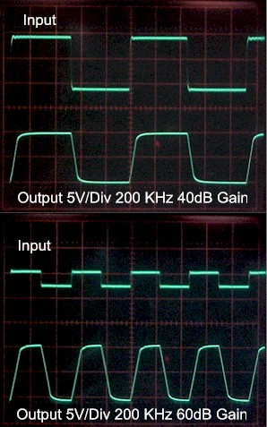
[quote author="mediatechnology"]I had been looking for these 'scope photos of the THAT 1510 for months now. I probably didn't find them as soon as I could have because they were in an SSM2016 folder. Doh!

When I first got samples of the 1510 I wanted to check the squarewave response at high gains. This is where the SSM2017 really began to crap out on bandwidth. So I did a 20 KHz squarewave test at both 40 and 60 dB gain as well as a 200 KHz torture test to see how well the part behaved. Now I didn't expect 200 KHz at 60 dB gain to be pretty. In fact I thought it might come unglued. But it didn't. The 1510 is very well behaved. Having a 3 MHz -3 dB bandwidth at 60 dB gain pays off.


1510_200KHz_Comp.jpg
[/quote]

Warning.. the following is a personal design philosophy and perhaps not problematic for most application. Those scope photos bother me somewhat. I agree the 1510 looks very well behaved indeed. The recovery coming out of slew limiting looks as good as I've seen.

My personal design philosophy is to LPF signal inputs at a high enough pole frequency to not impinge on the audio bandwidth, but low enough to prevent slew limiting for any valid (unclipped) sine input.

The lads at THAT don't publish a power bandwidth spec (max clean FS sine wave frequency) but working from their slew rate it's probably somewhere above 600 kHz. So any input LPF lower than that would make me happy. :grin: Their published app note input termination of 2x 470pF in series misses that by a factor of 10x :cry: (-3dB @ 4.5 MHz for 150 ohm). I suspect I may not get much support from audiophiles but I would and do use more input capacitance than that.

In my ideal world the square wave would exhibit an exponential rise time which would be independent of square wave voltage, i.e. not slew limited. Whenever you encounter slew limiting the output is by definition not following the input. This 1510 looks very well behaved when recovering from slew limiting but say instead of a square wave causing that slew limit it was RF interference. That same slew limiting would rectify the RF generating potentially audible artifacts. A simple input LPF could make it not have to. The excellent GBW of the 1510 means this passive LPF could be set pretty high (< 600 kHz) and still be effective.

I repeat this is not a huge deal, and that part looks great, but my wider philosophy regarding any audio path is to either cleanly pass or benignly roll off all possible inputs. Mic preamps routinely get exposed to RF etc.

JR

Note: From observation if you look at the transition from slew limiting to linear response on the scope photos you will see a small region of exponential response where the internal compensation pole is providing the effective LPF, ideally you want the entire waveform rise time to look like that small post slew transition region when hit with any level square wave. [/rant]
 
[quote author="mediatechnology"]
Their published app note input termination of 2x 470pF in series misses that by a factor of 10x

John - Do you suppose that this value choice is due to the fact that the 1510 and similar parts are sometimes used as combo mic/line inputs that might be driven by higher source impedances than 150 ohm?
[/quote]

Typically when mic preamps are used for mic/line applications there is a resistive pad to terminate the line higher, while dropping down to mic signal level and impedance for decent noise in the preamp. I can't justify the 4.5 MHz input pole, so I won't try.

In a mic-only application shouldn't an LC input filter be considered for RF immunity?
LC is better if well executed. In high RF you need to also be sure magnetics don't saturate etc. Caps are cheap and well behaved in those (film) values.

And wouldn't a SSM2019 or INA-XXX be just as bad if not worse with their lower bandwidth with the same input network?
Slower parts would be that much worse and require even tighter input filters. The 1510 is a good looking part and my comments are more about the application than the part.

BTW we are hit hard here by WBAP 820 KHz (tens of millivolts) and I've never witnessed any rectification. My test circuits usually have 470 pF tip-ring.
If the amplitude of the RF is modest at the preamp it will probably pass cleanly to be hopefully rolled off in a later stage. With a power bandwidth of 600kHz it could output several volts Pk-Pk at 860kHz. Are you seeing ten's of millivolts differentially at input? At 60 dB gain that seems like it could be a problem. Just like the slew limited square wave signal cleans up in the transition region as it comes out of slew limiting there is some inherent LPF from the chip's compensation/GBW.


BTW: The objective with the 200 KHz test was to put it into slew limiting to see how it handled it. Small-signal bandwidth at 60dB gain is maybe 3 MHz.

Agreed, good looking part.. I am stating a personal design preference that if properly executed leads to a very clean and robust signal path. The vast majority of designs do not follow my design philosophy. In my (dream) world products don't have slew rates, they have rise times. Were I using the 1510 I'd be inclined to make the input pole in the 250-400kHz region, YMMV.

JR
 
[quote author="mediatechnology"]
Are you seeing ten's of millivolts differentially at input?

I suspect it's common-mode. (I don't see significant amplification of it.) It's everywhere so hard to tell. I think a lot of it is conducted in via ground. We're near a transmission line that re-radiates it. Even a short wire loop gives plenty of 820. For a mic preamp it's a pretty hostile environment. But I've never herad any rectification of it.

Was looking at TI's INAs and they don't show any RFI protection at the input but they do show an LR network to prevent INA oscillation with <10 ohm source impedances. In the PGA2500 app they show a "T" network like THAT's with 1000 pF Cs.[/quote]

My question was pretty much rhetorical since tens of mV at input would be tens of volts at output.

For the record this looks like a great part, my experience just makes me a little conservative about dealing with out of band signals. I recall an early console design of mine back in the '70s getting installed in a studio less than a mile from an AM tower (960 kHz). Wonder why I remember the station frequency! :roll: Long story for another time.

JR

PS: The ESL of a big honkin electrolytic cap in the gain leg might help here, especially with slower designs. :wink:
 
I am not a huge fan of running opamps non-inverting unity gain, while the 2604 is probably quite good. They spec the input common mode similar to the output swing so it's not a headroom issue.

I'd be tempted to just lose the buffer and go right into the inverting gain trim, but with 1uF cap that might be getting close to a noise floor issue.

I'm sure it's fine as is, just rearranging the angels on a pinhead.

JR
 
I'm curious to hear what you find out about real-world microphone differential voltage offsets. I've heard rumor of bizarre asymmetrical output topologies and wonder how they would affect your circuit, but I don't have any direct experience with them. I hate to name names because I'm going off vague memories of anonymous old usenet posts, but I want to say that the TLM103 maybe has an asymetrical (AC) output and that the Behringer measurement mike (which people seem to like on drums) has an intentionally asymmetrical phantom current draw. Don't quote me on this, but I might suggest these two microphones for a closer look.

Personally, I was most concerned that your vactrol circuit would mess up audio CMRR while trying to compensate DC offset of the preamp's active devices, so I'm glad you went back to the current feed approach which I like.

Another observation I have might be best saved for another thread but I'm going to dump it on you here anyway. At the very outset of this thread, you described your interest in ditching the input coupling caps as an effort to make the preamp fit the microphone, rather than vice-versa:

How about making the preamplifier accommodate the microphone?
So my thought while reading these nine pages of discussion was constantly, "Why not go get the microphone and nail it down?"

The idea of using just one preamp for a particular microphone seems like heresy today when everybody wants unlimited tonal variety and open-ended options. But when you're specifically after neutrality (which you seem to be here) then there's not really room for variety - any tonal variation between "neutral" preamp would be to the degree they failed at being neutral. So rather than selecting a preamp to fit the tonal requirements, we can call that a non-variable. Instead, I'd like to suggest we tailor the preamp to the particular microphone being used. This affords an excellent opportunity to eliminate a bunch of other variables. In the case of your design concept, the common mode input voltage gets much simpler to accommodate if you know the current draw and source impedance of the microphone. Heck, you should also know the differential DC voltage of the mike too, or at least its realistic range. Beyond that, you'll know the mike's sensitivity, noise floor, and overload SPL, so you'll also know the gain range and input signal conditions. I think most of us probably have relatively few mikes we'd grab from our personal collections when we're going to record something and attempt to achieve utmost neutrality. Since DIY is all about customization to your own needs, this doesn't strike me as impractical at all - whereas in the commercial world it would be another story altogether.

Taking this thought to its logical conclusion, I suppose you would start with your ideal microphone capsule and design the mike's electronics, the preamps, and an ADC (or record head driver) as an integrated system. You might even know where you're going to be putting that microphone and what sounds are going to reach it.

But this concept could also be as simple as building one preamp to accommodate phantom-powered mikes (you wouldn't need a +48 switch at all) and another preamp that doesn't even supply phantom power. Both could go without input coupling caps, and you would need fewer compromises if one circuit doesn't need to do both.

And finally, I'd like to thank everybody for the extensive discussion of the 1510. I had been thinking of doing something with this chip, and now I'm feeling more motivated to get on it.

Cheers,
 
[quote author="mediatechnology"]Quoting myself again :roll:
The 1 uf NP film I've chosen for my prototype is a Vishay/Roederstein Polypropylene and I wanted it lightly loaded. With no LF cut, the corner is about 2 Hz. I suppose that for low squarewave tilt we could use a 1M bias resistor with a noise penalty.

Yesterday was warm and I had a chance to do some thinkin' on the bike trail:

Why not bootstrap the coupling cap to raise the effective AC resistance of the 100K bias resistor? I mean we could get some really low squarewave tilt without the noise penalty of the 1M. Worth trying...

Now we'll probably throw most of that LF response away on a vocalist but on kick drum it might be awesome.[/quote]

Keep in mind the 1M is in parallel with the 1uF so the actual noise contribution in the frequency band where our hearing is sensitive will be much less.

I vote against the complexity as not worth the benefit (vLF noise).

JR
 
I ship products with PC-mount power transformers and I've never had one shear off. I use a low-profile torroidal power transformer (low profiler = less leverage), and it also has a threaded hole in the middle so you can fasten it to the circuitboard with a single screw in addition to the solder points. And of course the torroid is great for low emissions inside the box where your sensitive mike preamp circuitry is located.
 

Latest posts

Back
Top