Hey all! I'm nearing the end of this journey, but seem to have hit a snag. Here's a shot of my project as it currently stands:
[IMAGE REMOVED by author to avoid "copycat" failure.]
Earlier today, I seemed to be getting sound out of one of my PCBs - the one furthest to the right. However, something seems to have gone awry and, as a result, I'm no longer getting sound from anything. At this point, my suspicion is that the PSU is having issues; it's also possible that my grounding scheme isn't airtight. (I arrived at it after eyeballing a lot of other Access 312 builds on Google and Reverb, as well as in this thread.) That said, I wanted to lay out the project here and troubleshoot before arriving at any rash conclusions. This will be a little image-centric...
POTENTIAL PROBLEM #1: POWER/GROUND WIRING
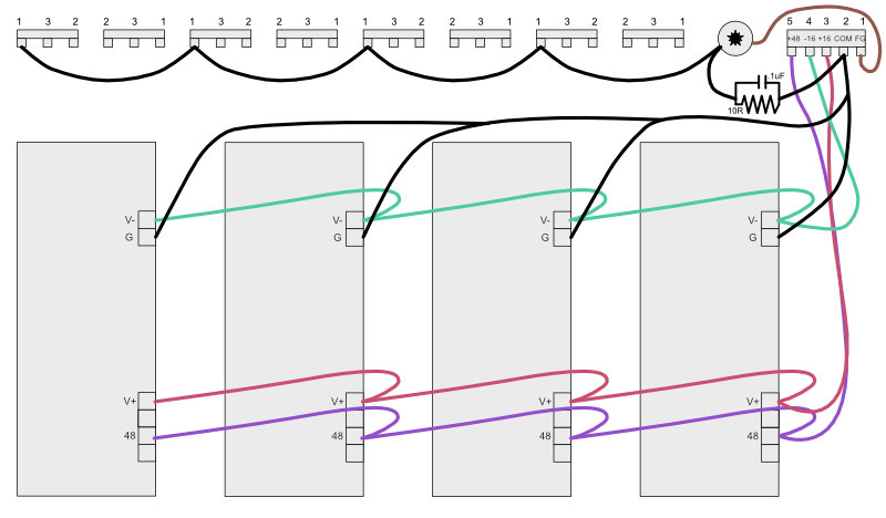
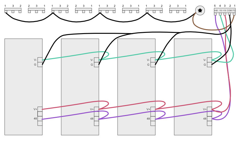
SO, here is my current power/ground wiring diagram:
[IMAGE REMOVED by author to avoid "copycat" failure.]
As far as POWER goes, daisy chaining seems to work. I have tested continuity across each board's rail screw terminal (V-, V+, +48) and found them to be consistent. (The voltage numbers themselves are a bit weird... more on that in a second.) In practice, this looks like:
[IMAGE REMOVED by author to avoid "copycat" failure.]
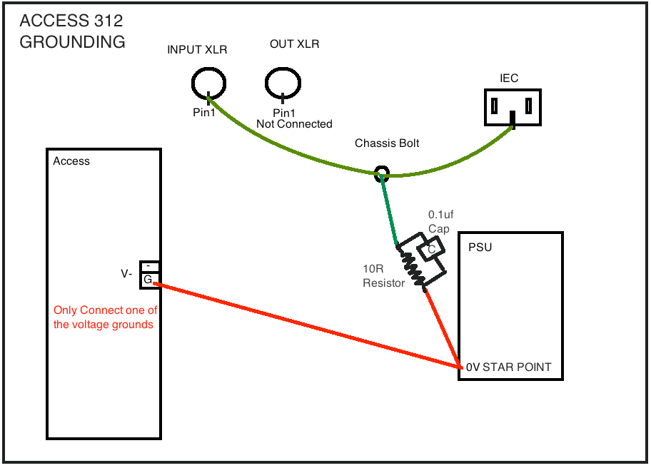
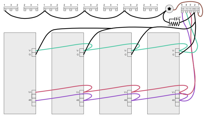
I initially attempted to daisy chain the COMMON GROUND, but was warned away from that approach by a 3nity comment earlier in this thread. The grounding scheme shown above was adapted from both Whoops (though I did skip the 10R resistor and .1uF cap, as they didn't figure into other folks' diagrams) and another seemingly successful build I found somewhere between pages 20 & 25. In practice, it looks like:
[IMAGE REMOVED by author to avoid "copycat" failure.]
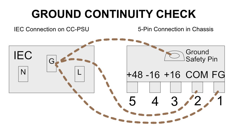
Also, as suggested by literally everybody, I connected the whole shebang to star ground using a blend of 3nity and Whoops' approaches:
[IMAGE REMOVED by author to avoid "copycat" failure.]
SO, that's one potential issue: I didn't wire things properly. If so, let me know! I've already miswired two major parts of the project at different points - the hot & cold on the 3-pin female XLRs and, likely more egregiously, the 5-pin XLR power jack. In the former case, I feel somewhat safe assuming that I didn't blow up anything (though I did test the +48 while it was wired backwards, so maybe that assumption's not so safe). In that latter case? Well...
POTENTIAL PROBLEM #2: MY PSU IS SHOT
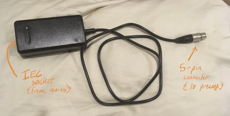
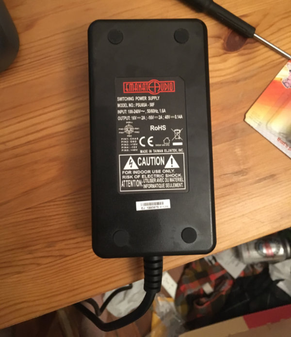
I'm using this PSU, the "CC-PSU" from Collective Cases:
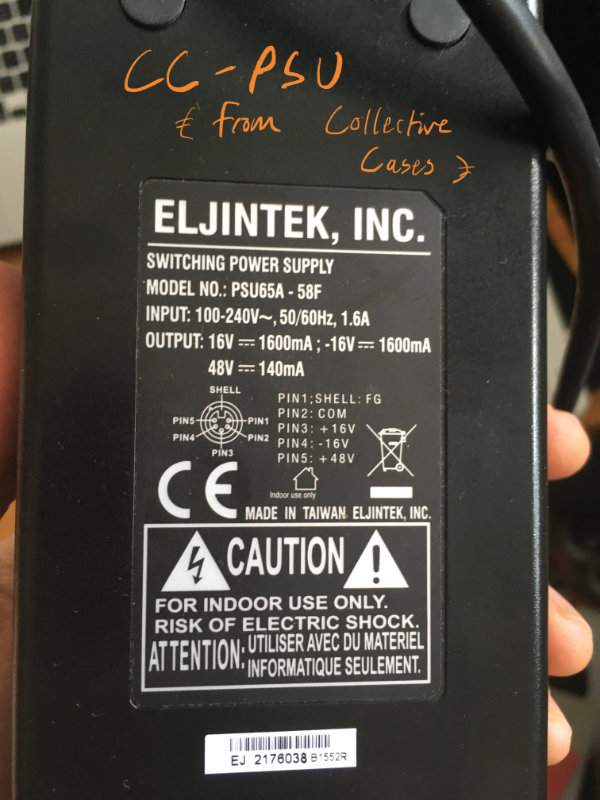
Now, you'd think that an external PSU would limit my ability to completely foul up the power situation, but I'm an idiot and can foul up almost anything. The CC site lists the PSU's pinout as the following:
PIN1: SHELL:FG
PIN2: COM
PIN3: +16V
PIN4: -16V
PIN5: +48V
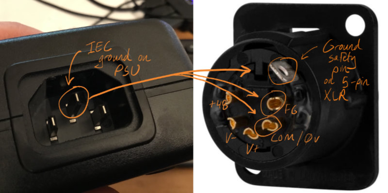
As you can see above, the PSU itself goes into further detail, providing a diagram of said pins. However, I somehow managed to never give the PSU a careful look, so that info was lost on me. Instead, I looked up "5-pin XLR pinout" online and merged that semi-meaningless information with the list on the CC site and.... wired the power connector backwards.
I know, I know... it's almost comically stupid. And, after a night of scratching my head at the weird clicking noises emanating from my pres, glaring at my multimeter, and rearranging my grounds/etc., I finally glanced at the PSU and, realizing my dumb mistake, rewired the 5-pin XLR:
[IMAGE REMOVED by author to avoid "copycat" failure.]
I tested the new wiring on one preamp and, for 15 glorious minutes, I finally got the voltages (~+/-16V & +48V) I expected/needed. I even used the 48v to power a condenser. And then... things took a turn for the worse.
After my modest success, I put the preamp back on my bench, and daisy chained the rest of the preamps to their appropriate rails. But when I came back, the preamps - even the one that had previously worked - were soundless. Even more perplexing, the rails that had been blasting +16, -16, and +48 with ease were now producing very strange (and choppy) voltages:
+48: 55.9V
+16: 0.9V to 1.9V
-16: -0.3V to -1.55V
SO, that's another potential issue: my PSU might have just bitten it. (Side note: Beyond the weird voltages, its "power on" LED seems dim - not a great sign.)
I'm not quite sure what my next move should be. Ordering a new PSU seems somewhat obvious, but I want to make sure that my wiring is tip-top/nonviolent before plugging another $75 power supply into this thing. That in mind, a few questions:
+ Am I on the right track in thinking that the PSU is the reason I'm getting no sound? If voltage is too low, do the preamps simply not work?
+ My XLR input hots/colds were wired backwards and I ran +48 through one of them. What might be the ramifications of this?
+ Does my current wiring look right? I assume my PSU went wonky because I initially wired the 5-pin XLR incorrectly, but if there's something else afoot, I'd like to know.
+ Given that I wired the rails incorrectly the first time around, should I be worried about my preamps? There are no exploded caps or smoking resistors, not enough heat went through the switches to really cause an issue, txers could probably withstand an atomic blast. My only concern is the DOAs, and then only because they're full of transistors - but, again, no smoking. What parts of the boards should I eyeball?
Sorry for the long post! Thanks in advance - any help you could provide would be beyond appreciated.
[IMAGE REMOVED by author to avoid "copycat" failure.]
Earlier today, I seemed to be getting sound out of one of my PCBs - the one furthest to the right. However, something seems to have gone awry and, as a result, I'm no longer getting sound from anything. At this point, my suspicion is that the PSU is having issues; it's also possible that my grounding scheme isn't airtight. (I arrived at it after eyeballing a lot of other Access 312 builds on Google and Reverb, as well as in this thread.) That said, I wanted to lay out the project here and troubleshoot before arriving at any rash conclusions. This will be a little image-centric...
POTENTIAL PROBLEM #1: POWER/GROUND WIRING
SO, here is my current power/ground wiring diagram:
[IMAGE REMOVED by author to avoid "copycat" failure.]
As far as POWER goes, daisy chaining seems to work. I have tested continuity across each board's rail screw terminal (V-, V+, +48) and found them to be consistent. (The voltage numbers themselves are a bit weird... more on that in a second.) In practice, this looks like:
[IMAGE REMOVED by author to avoid "copycat" failure.]
I initially attempted to daisy chain the COMMON GROUND, but was warned away from that approach by a 3nity comment earlier in this thread. The grounding scheme shown above was adapted from both Whoops (though I did skip the 10R resistor and .1uF cap, as they didn't figure into other folks' diagrams) and another seemingly successful build I found somewhere between pages 20 & 25. In practice, it looks like:
[IMAGE REMOVED by author to avoid "copycat" failure.]
Also, as suggested by literally everybody, I connected the whole shebang to star ground using a blend of 3nity and Whoops' approaches:
[IMAGE REMOVED by author to avoid "copycat" failure.]
SO, that's one potential issue: I didn't wire things properly. If so, let me know! I've already miswired two major parts of the project at different points - the hot & cold on the 3-pin female XLRs and, likely more egregiously, the 5-pin XLR power jack. In the former case, I feel somewhat safe assuming that I didn't blow up anything (though I did test the +48 while it was wired backwards, so maybe that assumption's not so safe). In that latter case? Well...
POTENTIAL PROBLEM #2: MY PSU IS SHOT
I'm using this PSU, the "CC-PSU" from Collective Cases:

Now, you'd think that an external PSU would limit my ability to completely foul up the power situation, but I'm an idiot and can foul up almost anything. The CC site lists the PSU's pinout as the following:
PIN1: SHELL:FG
PIN2: COM
PIN3: +16V
PIN4: -16V
PIN5: +48V
As you can see above, the PSU itself goes into further detail, providing a diagram of said pins. However, I somehow managed to never give the PSU a careful look, so that info was lost on me. Instead, I looked up "5-pin XLR pinout" online and merged that semi-meaningless information with the list on the CC site and.... wired the power connector backwards.
I know, I know... it's almost comically stupid. And, after a night of scratching my head at the weird clicking noises emanating from my pres, glaring at my multimeter, and rearranging my grounds/etc., I finally glanced at the PSU and, realizing my dumb mistake, rewired the 5-pin XLR:
[IMAGE REMOVED by author to avoid "copycat" failure.]
I tested the new wiring on one preamp and, for 15 glorious minutes, I finally got the voltages (~+/-16V & +48V) I expected/needed. I even used the 48v to power a condenser. And then... things took a turn for the worse.
After my modest success, I put the preamp back on my bench, and daisy chained the rest of the preamps to their appropriate rails. But when I came back, the preamps - even the one that had previously worked - were soundless. Even more perplexing, the rails that had been blasting +16, -16, and +48 with ease were now producing very strange (and choppy) voltages:
+48: 55.9V
+16: 0.9V to 1.9V
-16: -0.3V to -1.55V
SO, that's another potential issue: my PSU might have just bitten it. (Side note: Beyond the weird voltages, its "power on" LED seems dim - not a great sign.)
I'm not quite sure what my next move should be. Ordering a new PSU seems somewhat obvious, but I want to make sure that my wiring is tip-top/nonviolent before plugging another $75 power supply into this thing. That in mind, a few questions:
+ Am I on the right track in thinking that the PSU is the reason I'm getting no sound? If voltage is too low, do the preamps simply not work?
+ My XLR input hots/colds were wired backwards and I ran +48 through one of them. What might be the ramifications of this?
+ Does my current wiring look right? I assume my PSU went wonky because I initially wired the 5-pin XLR incorrectly, but if there's something else afoot, I'd like to know.
+ Given that I wired the rails incorrectly the first time around, should I be worried about my preamps? There are no exploded caps or smoking resistors, not enough heat went through the switches to really cause an issue, txers could probably withstand an atomic blast. My only concern is the DOAs, and then only because they're full of transistors - but, again, no smoking. What parts of the boards should I eyeball?
Sorry for the long post! Thanks in advance - any help you could provide would be beyond appreciated.


