3nity
Well-known member
Cinemag CMOQ-2s.
Jensen? sowter?
Jensen? sowter?


3nity said:Cinemag CMOQ-2s.
Jensen? sowter?
")
toneboner said:@sr1200 -- totally jealous. even with ur weird 48v voltages ur well on your way. i'm still saving up the scratch for my cinemags...! what are using the 12v rail for?
@micdaddy -- the bom i posted was from another thread (cant remember!) and will stuff 4 boards + extras. Itd be nice to know what someone else thought of the parts -- errors, advice or substitutions...
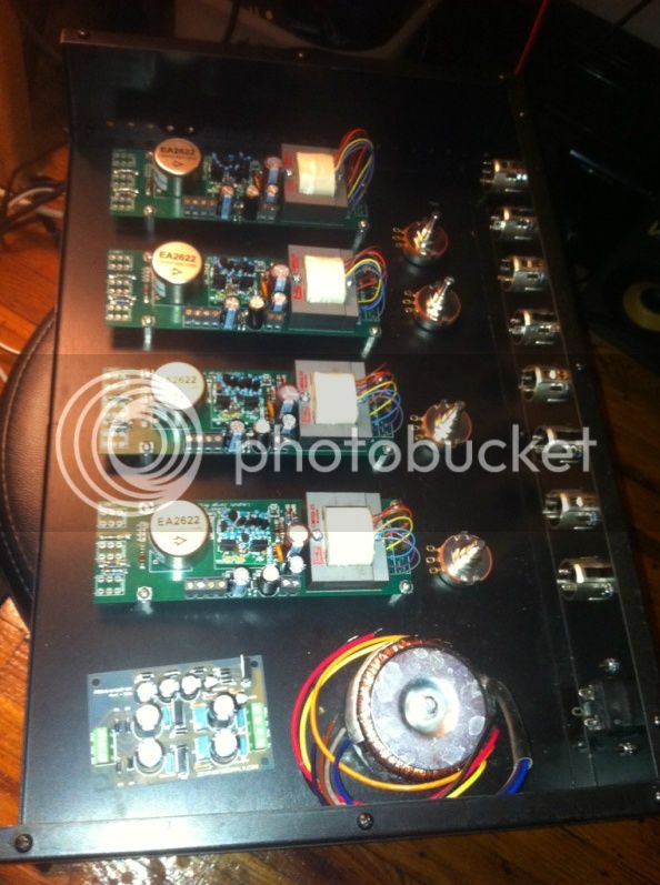
sr1200 said:I used the whistle rock PS with an avil lindberg trafo. I've read that the DIYpartssupply PSuniversal can be used as well (i needed an extra rail for my VU meters)
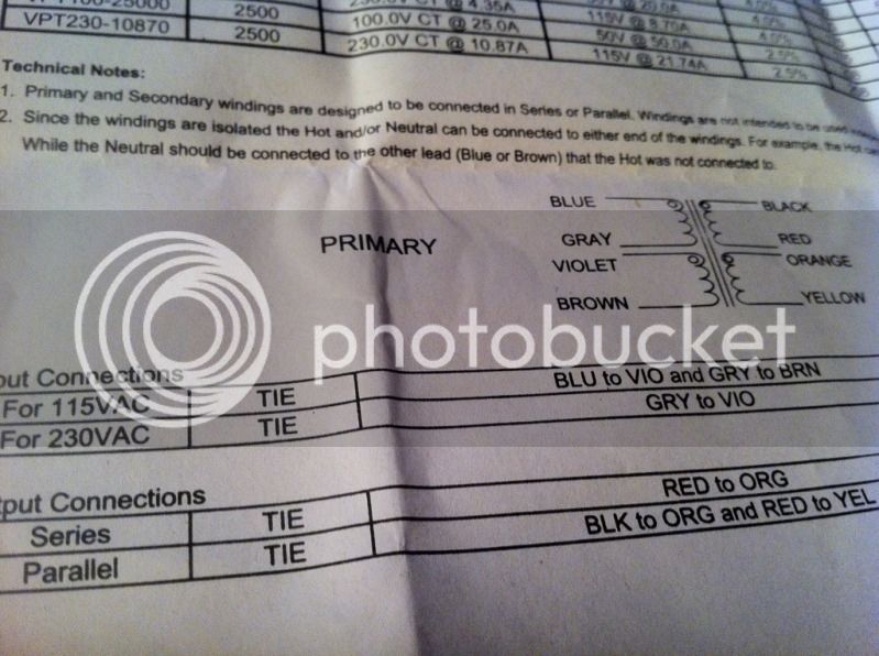
3nity said:Transformers Antekinc.com is really cheap priced and well done.
PSU is diypartssupply good and efficient as well as affordable.
Thanks.


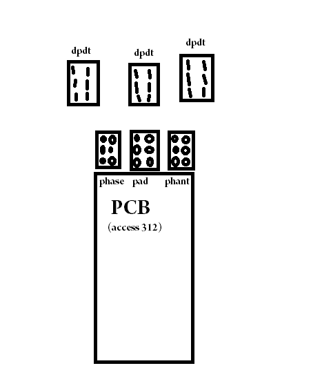
buildafriend said:For the XLR ins and outs; should I only connect hot and cold? I am used to sending the wires shield to the board as ground... I need to learn how all this transformer balancing stuff works. The board does not have any input pad/terminal for my shield.
What pins do the gain pads connect to on my pots?


