Advice and ideas for a mixing console build

GroupDIY Audio Forum

Help Support GroupDIY Audio Forum:

This site may earn a commission from merchant affiliate links, including eBay, Amazon, and others.
Just made a fader module prototype.. it's 165x40mm so it can house a 100mm fader no problem (given that it isn't higher than 35mm) without making modifications to the frame.

According to specs ALPS 100mm faders have 120mm mounting hole spacing with 128mm overall depth... I think I can fit a solo button there too.
 
Look, again, not trying to be mean, but please look at how commercial designs implement what you want to do, and learn from them first. At the very least, add some buffering between your "eq" circuit blocks. As of now, your channels are just big load dependant messes. Your eq points will shift depending on what you have patched into the insert, and depending on where you have the other band set.

Have you considered any of the advice people are giving you in this thread?
 
Most of us here are willing to help you, but you have to take constructive criticism. Starting out in electronics is a super brutal learning curve.

.....or you can go ahead and build a mixer that makes a shure M68 look like a Neve.  ;D
 
I've also been thinking of implementing a reverb in the build.. found some spring reverb tanks and adjustable digital modules.

I think a HPF is a must with reverbs in order not to muddy the sound... most need a buffer of some sort too in order to work correctly.

EDIT : another thing is input transformers.. gets very expensive quickly though.
 
boji said:
I asked if you wanted to avoid tx's.  Also suggested you look at design notes by THAT.

Sorry...I interpreted tx as transmit (tx/rx as in digital/radio communication)
 
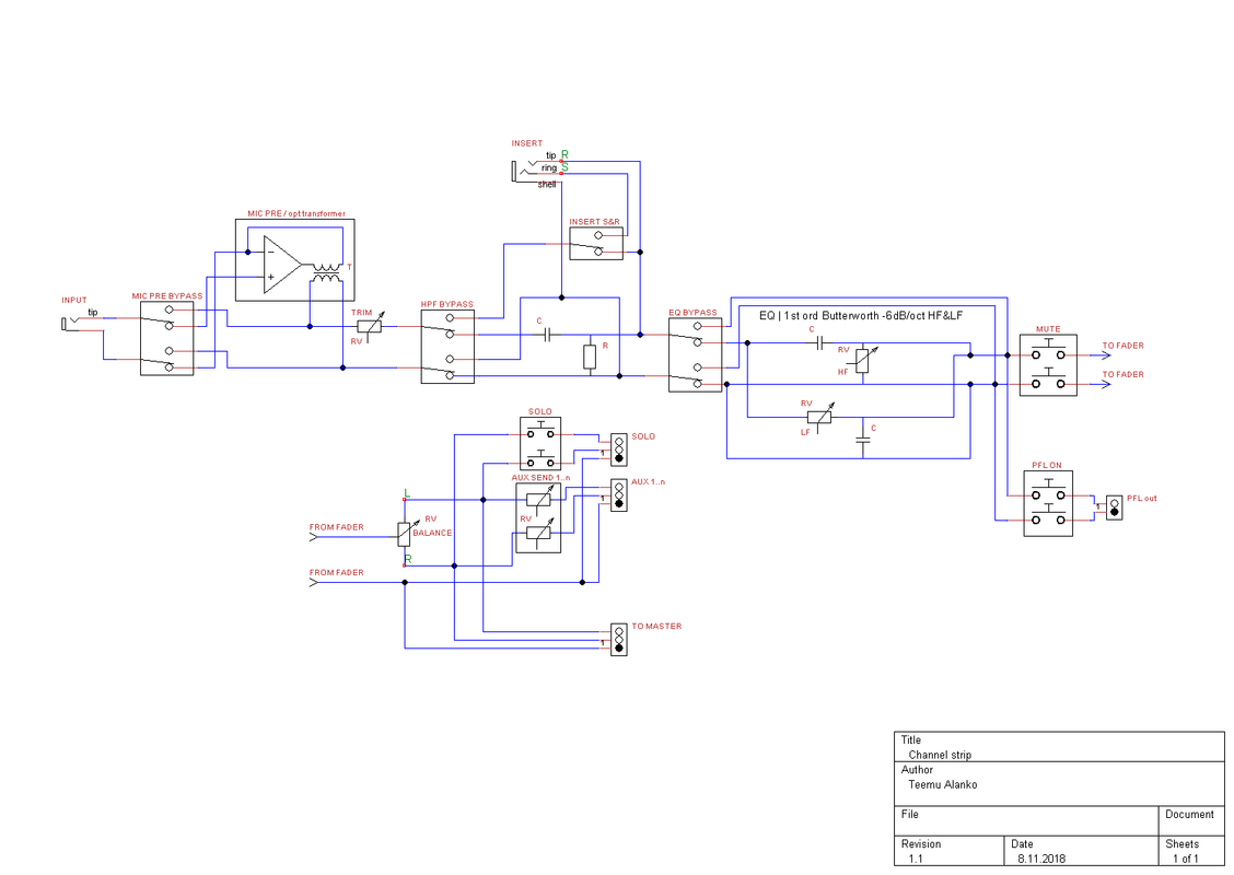
Here's the revised channel strip schematic..

chstrip1-1.png


I was trying to come up with a solution for a pre/post aux send, however to do so I'd probably need to reposition the balance controls pre-fader; this in turn calls for stereo faders... it could be a useful feature though, go figure.

EDIT : I think one way to compensate for the loss of volume from the faders using post aux send would be to buffer the aux channel..

EDIT 2 : or use the PFL to set up a monitor mix.. it has no level control though.
 
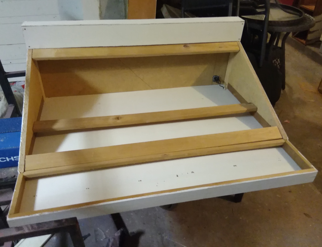
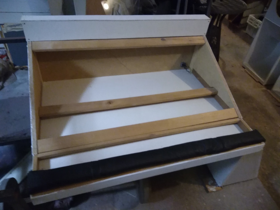
Here's a pic of the frame painted, I also put an IEC (=mains) connector & fuse box in there the other day :

IMG-20181108-190913.jpg
 
Your input jack is mono; do you in fact want your micpre only able to receive unbalanced in?

On an insert jack, typically tip is send, ring return.

Also pretty sure you don't need to include com in the switches since no mater when you send signal, it's still referencing it.
As mentioned before, where are your symbols to com?

It's a little weird that insert is dependent on hpf being bypassed. Why not put it after hpf option?


boji said:
Your input jack is mono; do you in fact want your micpre only able to receive unbalanced in?

Good question... I made the schematic for illustrative purposes only, ie. to clear things up. Sometimes designing is easier when you draw it.

On an insert jack, typically tip is send, ring return.

Depends on the equipment I guess. Other than that; semantics, and it's easier to draw it that way.

Also pretty sure you don't need to include com in the switches since no mater when you send signal, it's still referencing it.
As mentioned before, where are your symbols to com?

I take it you mean ground with com. I stated earlier that a dual switch is far more robust so why not use the other pole for ground. Balanced mixer is an overkill imo.

It's a little weird that insert is dependent on hpf being bypassed. Why not put it after hpf option?

I think an insert with HPF isn't necessary.. it's for microphone low cut really.

Anyway, today I breadboarded a mid band EQ with great success. I'll add it to the schematic with some minor fixes once I get around to it.
 
I made the schematic for illustrative purposes only,
You get what you give (Often wonderfully not the case around gdiy).

On an insert jack, typically tip is send, ring return.
Depends on the equipment I guess.
If you lose the convention you'll have to make crossover cables for 3rd party single-jack fx loop gear.

I take it you mean ground with com. I stated earlier that a dual switch is far more robust so why not use the other pole for ground. Balanced mixer is an overkill imo.
One of the benefits of unbalanced is that you can let com be 'common'.
No reason to design-in extra points of potential failure if things can work just as well without them.

I think an insert with HPF isn't necessary.. it's for microphone low cut really
So no mix-downs then, just tracking.


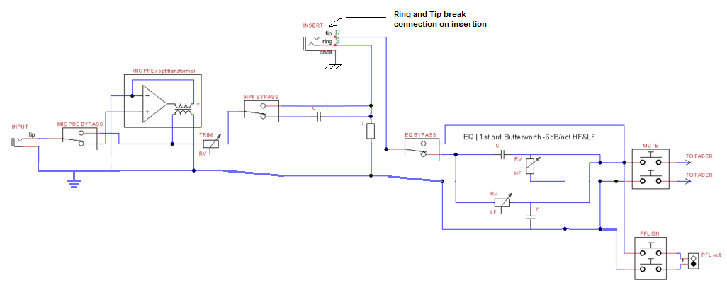
Mistakes may be present, but you get the gist:
m1sM02c.png


Edit: Also I'd add a way to isolate the tx from the signal path when not in use.
This would be a good spot to use a 2-4 pole sw with input selection vs tx dependency.
 
I don't have access to CAD or the files as of now since my desktop PC stopped working.
 
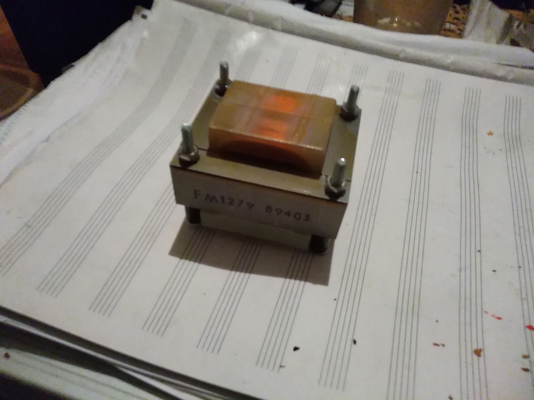
Pulled a laminated-core transformer from an old Teleste intercom..

IMG-20181230-061519.jpg


If I understood correctly the unit was used to multiplex/split a phone line in a hotel for rooms.

EDIT : in case it's not suitable I'll try it in an amplifier project instead.. which too is made from various parts I've scavenged. The problem is finding equivelant/matching spares because these things aren't easy to find or spec.
 
abhijit said:
thanks for sharingHello all we have facebook services that likes, comments, etc. if you have any requirement regarding this services you can contact us by visiting our site.  buy indian yo

300px-Bot%C3%B3n_Me_gusta.svg.png
 
efinque said:
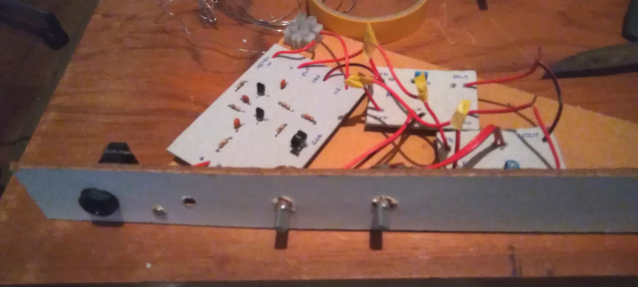
Here's a pic of a prototype channel strip in the making..

IMG-20181101-044459.jpg

Is this circuitry functional, and does it meet your criteria of passable quality?

If yes, then I think you have much more room inside your mixer frame than you'll need, even if you wind up having to squish those parts together a bit more. Though I'd certainly add my voice to the chorus regarding shielding, at least line the cavity with some aluminum foil.

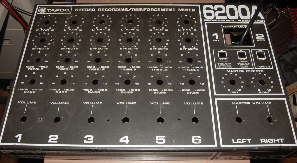
I'm sailing a similar craft in that I also have the hard limit of an exterior shell I'm planning to fill out, in my case it's an old Tapco 6200 enclosure.

cI1E2EA.jpg


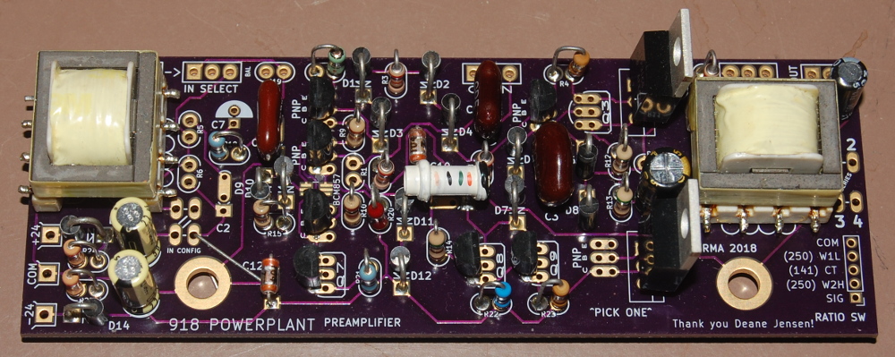
But I'm going to run into spatial constraints really fast, as I'm planning on starting my signal chain with a dumbed down Jensen 918 based discrete operational amplifier:

gjZMNNC.jpg


All of that functionality (make signal bigger now) could fit on a postage stamp with room to spare these days. But, my design goal is pretty simple. I want six mic preamps in a box with balanced direct outputs, and the added functionality of a dirty mix, so I think I'll be able to sleep at night when it becomes imperative to use some monolithic ICs for other stuff in the summing and sending stages.

Regarding the original post/title, I'm reluctant to offer advice on your build as it seems you are not receptive of ideas that are not loaded with confirmation bias - but I am happy to say that if this project is performing to your needs then you're on an okay path that will probably not be followed by most (which is where culling technical advice in the face of a problem becomes quite tricky).

Belay that: is there a trimpot labelled "Gain" on your input circuit? Why is that not a panel mount control?
 
crochambeau said:
Is this circuitry functional, and does it meet your criteria of passable quality?

It's a prototype.. like the circuitry itself.

If yes, then I think you have much more room inside your mixer frame than you'll need, even if you wind up having to squish those parts together a bit more.

Better to have enough than run out I guess.. makes troubleshooting easier too once (or if since I'm really busy) it's assembled.

Belay that: is there a trimpot labelled "Gain" on your input circuit? Why is that not a panel mount control?

It's a prototype for testing purposes.
 
efinque said:
It's a prototype.. like the circuitry itself.

In my experience a prototype is useless if not functional.

Does your prototype work, or is it just conceptual eye-candy?
 
crochambeau said:
In my experience a prototype is useless if not functional.

Does your prototype work, or is it just conceptual eye-candy?

Well, iirc it passed audio.. that's about it. (edit : there was something wrong with the filters I guess)


To save space I would rather use a separate, bypassable mic pre module about the size of a matchbox. The idea was to see how the modules would fit the channel strip, and they did; the problem is lack of resources and time (note that I'm also building a PA system)
 

Latest posts

Back
Top