Alembic F2B build 6N1P

GroupDIY Audio Forum

Help Support GroupDIY Audio Forum:

This site may earn a commission from merchant affiliate links, including eBay, Amazon, and others.
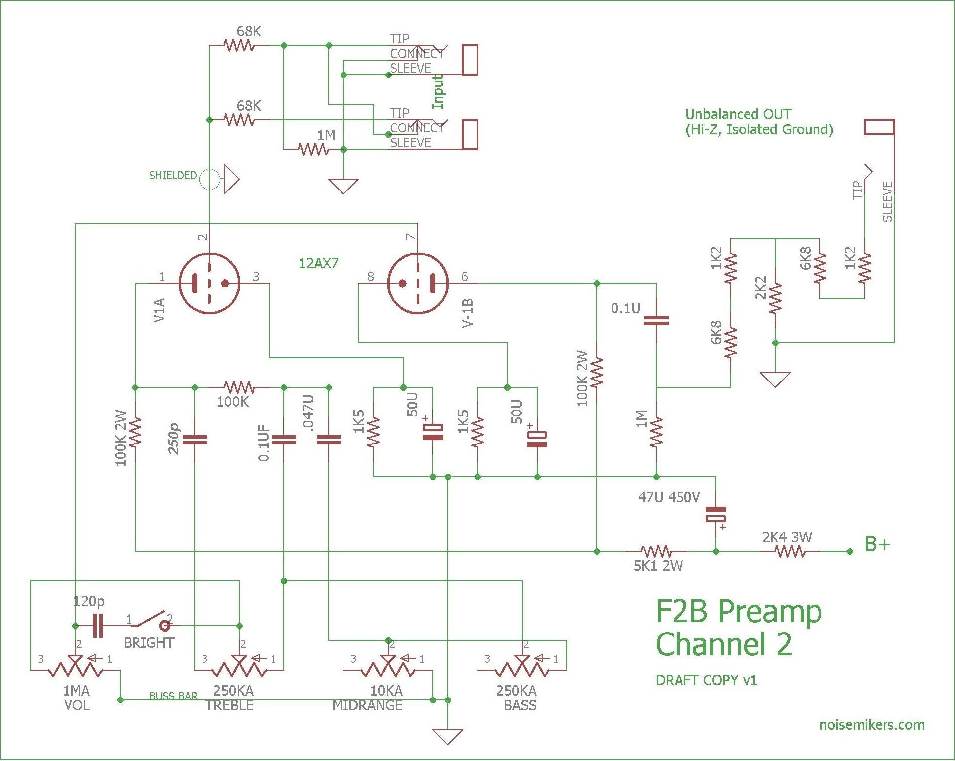
I'm assuming you just misnumbered? As it stands, you have cathodes connected to B+ and plates to the 1.5K cathode resistors...:)

Also there is strangeness in the final tube, as it looks like you have the cathode of one stage driving the plate of the next.

The 100nF leading to the unbalanced out isn't needed in the first diagram.
 
Yes I didn’t think that 100nf was needed but did see it as an option in another schematic, got mixed up.
And yes I misnamed the tube numbers!!
The cathode to the plate connection I though was weird but I’m sure it’s like that on the schematic?
 
That wiring in post #43 is non-sensical. The one on the noisemikers site makes sense but is different:

F2B-CH2-e1539689103479.jpg
 
Ultimately the cap size depends on the input impedance you want to drive and what pole you want in the filter response. 1K will look like 25K to the output (with a 5:1), so 2.2u into 25K passes over 2Hz which seems like a good level for something intended as a bass preamp. Even a vintage 600ohm input looks like 15K which is ~5Hz which seems ok as well.
 
Also note the "ground lift" in post #43 is incorrect: it is mixing pin 1 shield with audio 0V, which is (potentially) injecting a pin 1 problem unnecessarily. Pin 1 should go directly to the chassis: full stop. The only reason to possibly lift this connection to the chassis would be if this would end up driving an unbalanced input (but then why even use a balanced output, given you already have an unbalanced output?).

Chassis can connect to audio 0V, in only one place, and is best done right at the input jack.
 

Latest posts

Back
Top