All things Green Pre

GroupDIY Audio Forum

Help Support GroupDIY Audio Forum:

This site may earn a commission from merchant affiliate links, including eBay, Amazon, and others.
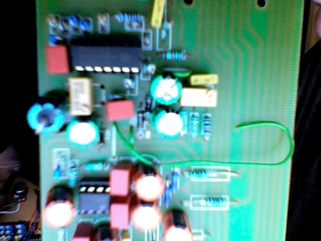
I'm having problems with the voltages on my green.

IC1 pin 7 and IC2 pins 1 and 2 all have 1.98V with +/-18V supply. I also have the same voltage on the input pins where the XLR will go. I don't have any phantom hooked up so I don't think I should have anything here.

All other voltages are apppropiate with the list of Voltages that Peter has supplied except for those 3. Nothing is connected and the opamps are out of the sockets.

I've checked this with both my power supply and 4 9 volt batteries. My first green works great with both of these.

I saw someone with the same problem on page 13 on this thread but there was no solution presented. I emailed him, he got his working but he doesn't remember how he fixed it.

I would be gratefull for any help.

Eric
 
Do you have a working channel? Sounds like it from your post.

Compare the DC voltages across the 2 channels, especially around the BC550's. Use a meter to check the protection zeners as well.

Peter
 
Thanks Peter! I do have one channel working and it sounds great! It is my first from scratch including the etching (you did all the hard work though, thank you very much) and I'm bouncing all over the place that it actually works!

I will compare voltages to the other board when I get home from work.

To anyone that can help I want to treat this as a learning opportunity. If this has been explained before, I can't find it.

I'm trying to figure this out on the schematic. Shouldn't the voltages be identical on the emitters of both the BC550s? And for that matter, on the top and bottom of the schematic through to U1? And if they aren't is the transistor the likely culprit?

Also there should be no DC in the section from c1 and c2 through c3 and c4 correct? I don't get any there and I don't think I should. The capacitors take care of blocking the DC. Does this mean that the Zeners are an unlikely culprit.

Thanks for any light that can be spread.

Eric
 
The Zeners that I get seem to be very inconsistent. Some 1/2watters have worked fine, some 3 watt items have gone faulty. So I personally use 5w parts in there now, they seem to be OK.

Peter
 
I got a friend into DIY and I've been sorta walking him along through his first project of 4 channels of green..

We finishd em tonight but on one channel 4 of the 10R resistors left of the TL074 IC / 4 10uf electrolytics on the layout burn up when I turn the unit on... It passes audio Just fine but then they fry.

The other 3 channels are working fine. I've checked the wiring and solder pads all is well.

Any ideas?

Thanks again for this project peter

best,

Richie
 
Photo50.jpg


I've replaced them just to double check and the same thing happened again.
Voltages are all ok also when I disconnect the broken channel. I tried to measure the opamp voltages when the broken channel is connected and I get around 40mv. The LEDs also show no life, on the broken channel. The TL074 gets slightly hot when the resistors burn up.
 
Hi anyone

A first post here, i hope people are still hovering around this thread.

Firstly Matta (and everyone thats contributed), thanks for looking after this Green metta. It's helped me through my first big DIY, a 4ch green. Also PeterC thanks for starting this whole thing up and Ptown thank for the kit.

Ok, so the problem..4 channels and psu done and all racked up. All channels are passing some nice audio, with a little white noise, a bit of hum of the channel nearest the toroid, but there isn't much i can do about this.

When it came to setting up, i noticed i'm not getting much output and and the output starts to distort at quite low gain. When setting the led meter levels and measuring the output from the + of the pre, I can't get any more than 3v ac. At around 2.5v ac it starts to distort.

This is the same on all channels which are otherwise ok. So i'm guessing this could be a PSU thing, or something i've not noticed and done the same on all channels. After searching the forum and reading around i have a hunch this could be related to the transistors being in the wrong way round (?).

Does anyone have any ideas or kind words of wisdom? I wouldn't be surprised if i've just totally missed the point of something, and am happy to be told this.

thanks
ed
 
I´m building up a 4-Ch Green as my first DIY-Project. all´s working perfectly, exept LED´s on Ch. 3 don´t light up when I got a signal on the input, but they light up when I turn the 20k Trim, so the LED´s are ok. All voltages (with or without IC) are perfect. Any help?

BTW, does anybody can send me a schematic?

Again, please excuse my english...
 
hi
in the BOM it states that the high pass filter is a SPST should it not be a SPDT. and if not how does a 2 leg switch go onto the 3 holes?

thanks for any info

mark
 
Hi again
on the pSU board there is some caps rated 47uf 100v and some 47uf 63v
do these have to be these ratings?
i was going to put 100v on all of them but just wanted to make sure it would be okay.
 
Has anyone tried some alternates to the TL074 or NE5532?
I was thinking of the LME49740 chip for the TL074, and its sibling the LM4562 for the NE5532 positions in the Green Pre.
Should be done the boards this weekend, and wanted to listen to different sonic flavors.
 
Hey everyone. I'm putting together the parts list for 2 Green Pre's & had a few questions.

There seem to be a lot of lists & different info out there because of the different versions, but I've come across a couple that I wanted to ask you all about first.

The first is here: http://recording.org/users/kev/green_parts.htm

The 2nd is an Excel spreadsheet that I downloaded from the "green pre docs" here: http://www.mendelt.nl/greenpre_V14/

I'm currently comparing the lists, but wanted to go ahead & ask if I'm on the right track so far. I have the V14 version of the boards.

Thanks in advance for any input!
 

Latest posts

Back
Top