You are using an out of date browser. It may not display this or other websites correctly.
You should upgrade or use an alternative browser.
You should upgrade or use an alternative browser.
All things Green Pre
- Thread starter HappyTom
- Start date


Help Support GroupDIY Audio Forum:
This site may earn a commission from merchant affiliate
links, including eBay, Amazon, and others.
kato
Well-known member
Nice build Hammond!
I like the unique LED meter layout!
I like the unique LED meter layout!
Thanks kato! ;D
I noticed that on one channel at first start up the first green led is on without a signal then after about 1 minute
the unit warms up and the led turns off. This happens because the voltage at the link behind the 10k pot
when i first turn on the green is 10mV, after warm up is around -3mV as it should.
Since having this led on without a signal for 1-2 minutes disturbed me i calibrated the 20k trim to turn it off,
but when it warms up the voltage drops to -20mV or so.
However i have found the led meters to work identical on both channels.
Should i leave everything as it is?
Can someone explain why on one channel the voltage starts so high then drops a lot?
Thanks in advance
peterc
Well-known member
I also get the "warm up" as well, but I have just eft hem where they are, all works fine.
To combat this, I should probably have used some kind of load on the input of the comparator.
Peter
To combat this, I should probably have used some kind of load on the input of the comparator.
Peter


![Electronics Soldering Iron Kit, [Upgraded] Soldering Iron 110V 90W LCD Digital Portable Soldering Kit 180-480℃(356-896℉), Welding Tool with ON/OFF Switch, Auto-sleep, Thermostatic Design](https://m.media-amazon.com/images/I/41gRDnlyfJS._SL500_.jpg)


mrphotodude
Well-known member
Another greenpre has been born!
Its v1, 4 channel.

here are the guts:
http://img15.imageshack.us/img15/2023/greengutsce1.jpg
and my nifty "petercornell designed"...giving P a shoutout there cause this unit just sounds damn good!
http://img300.imageshack.us/img300/8158/nameay8.jpg
I tried 5532's, 2604's, a few AD823's and a opa2134...
I ended up using 5532's in U1 and the 2604's as an output chip and i think it balances nicely and i am happy with it.
The regulators get pretty warm and i had some issues mounting them on heatsinks that were mounted to the chassis(problems isolating the chips properly!) so i ended up using two heatsinks back to back and it seems a bit better. http://img3.imageshack.us/img3/7895/heatsinkyy1.jpg
Bit of a squeeze on the board, but it works.
I was trying to calibrate it, but it does not seem to matter if i have any signal going into it or not! I am able to dial the cmrr to almost 0 measuring between ground and pin 1 of the output chip. I have a signal generator program i was running from my laptop through a cable with 2 resistors in a v like on the notes...with it or without the cable, seemed to let me dial it down.
It gets very gainy at about 8(my rotaries are 10 pos, i dropped out the lowest gain point and 1r5, swapped out the 2r for a 2r7 and that is the "floater").
at about 5-7 it sounds really great. I am running into a card that already has built in pre's though.
Does my way of calibrating it there sound totally off?
Its v1, 4 channel.
here are the guts:
http://img15.imageshack.us/img15/2023/greengutsce1.jpg
and my nifty "petercornell designed"...giving P a shoutout there cause this unit just sounds damn good!
http://img300.imageshack.us/img300/8158/nameay8.jpg
I tried 5532's, 2604's, a few AD823's and a opa2134...
I ended up using 5532's in U1 and the 2604's as an output chip and i think it balances nicely and i am happy with it.
The regulators get pretty warm and i had some issues mounting them on heatsinks that were mounted to the chassis(problems isolating the chips properly!) so i ended up using two heatsinks back to back and it seems a bit better. http://img3.imageshack.us/img3/7895/heatsinkyy1.jpg
Bit of a squeeze on the board, but it works.
I was trying to calibrate it, but it does not seem to matter if i have any signal going into it or not! I am able to dial the cmrr to almost 0 measuring between ground and pin 1 of the output chip. I have a signal generator program i was running from my laptop through a cable with 2 resistors in a v like on the notes...with it or without the cable, seemed to let me dial it down.
It gets very gainy at about 8(my rotaries are 10 pos, i dropped out the lowest gain point and 1r5, swapped out the 2r for a 2r7 and that is the "floater").
at about 5-7 it sounds really great. I am running into a card that already has built in pre's though.
Does my way of calibrating it there sound totally off?
mathflan
Well-known member
Hi mrphotodude,
Very nice work!
I finished my Green with 6 preamp few days ago.
I had some problems that I resolved ( I used some flat Computer Wire for the inputs, I had some buzz, I Remove all and put some Symetric cable.
The green is very quiet and sound awesome.
Perhaps less Presences or crystal High Frequency than my G9 preamp; it's not the same dsign.
I calibrated My green with a scope for the cmrr.
I wired the pin 2 with the pin 3 on a INPUT and putted a 1khz 20mv sinusoidal signal into it.
I checked the signal with the scope at Pin 1 of the Middle Ne5532.
I turned the Trimpot until the sinusoidal became flat.
I have some questions :
First, I Put Led indicator for the 48 volt.
I Have a Voltage Buzz when I put 48 volts on two preamp.
DO you have an idead?
-I used a 50 Va ( 1,66 A ) toroidal transformer
-I used Two PSU board which powered each Three Preamp
-Ground of inputs and outputs wired to the metal rack with earth and Ground supply.
- I put a 1 watt 8,2k resistor to tho first pin of the 48 volt switch and + Pin of the led and I wired the minus pin to the ground.
Secondly; When I have no signal the -40db green Led is light is it normal?
Thank you
I will post soon some pics of my work
Mmath
mathflan
Well-known member
Ok, The answer was in this thread ::
I should change the three 47uf capacitors of the PSU in order to remove the buzz from the 48 volt led.
another question,
When I turn the trim pot, So when I attenuate the signal,distorntion appears.
I have this on all channels.
I am wondering if My wiring was right for metering before the trim pot,
I have wired the two links at the left of the 100K trimmer.
I put in link from the single hole above the 20 k trimmer to the right end of the link ( wich wired 47 uf to 100nf capacitors) so the the 100 nf capacitor.
Am I right??
Thansks
Richon
Well-known member
I did change the 10uF electros in the path of the 48V PHANTOM in the Green PCB to 100uF to eliminate the buzz/noise/hum ..... tinny little secret, but works perfect now.
peterc
Well-known member
Secondly; When I have no signal the -40db green Led is light is it normal?
Just trim the 20k trimmer until it goes away.
mathflan
Well-known member
Thanks peter and Richon ")
Could you confirm if my wiring ( blue wire ) is right for mesuring Level before the output trim:

Is it normal that I have a Oscillation sound when I activate the HPF switch with the output trim at max, this oscillation disseapear when I turn a little the trim pot (anticlockwise).
Thanks
math
Could you confirm if my wiring ( blue wire ) is right for mesuring Level before the output trim:
Is it normal that I have a Oscillation sound when I activate the HPF switch with the output trim at max, this oscillation disseapear when I turn a little the trim pot (anticlockwise).
Thanks
math
mathflan
Well-known member
Ok, I found why I have got some distortion noise with the Trim pot.
In fact I Forgot to remove the first link which is on the left at the 100k trimmer pot.
NO more noise
I recheck the Voltage across the link on the left of the Trim pot and ground for the RC peak offset and the yes, The Values have changed, I trimmed the 20 K pot so as to have -3mv.
Now It's ok.
In fact I Forgot to remove the first link which is on the left at the 100k trimmer pot.
NO more noise
I recheck the Voltage across the link on the left of the Trim pot and ground for the RC peak offset and the yes, The Values have changed, I trimmed the 20 K pot so as to have -3mv.
Now It's ok.
mathflan
Well-known member
I took a look on the amek 9098 schematic :

I'am wondering if there any possiblities to add another preamp gain like on the new amek 9098 preamp so as to have a fine setup for the +6db range.
From the pdf's amek :
http://www.amek.com/products/dma/RNDMA%20brochure.pdf
"The variable Trim control has a range of +/- 6dB allowing fine
gain adjustment between the 6dB switched gain steps. It also
allows the gain to be extended by 6dB at either end giving an
overall gain range of -6dB to +72dB."
thanks
Math
Harpo
Well-known member
Hi Math,
for the amek9098 alike, two ways to get there:
1st. (probably easiest/affordable/sourcable) debalancer at unity gain, followed by an inverting variable gain stage with voltage gain varying between 0.5 and 2, might/should be followed by a transformer- or other driver for beefy/balanced out if needed.
2nd. (expensive) two non inverting gain stages with voltage gain of 2 each to get your +12dB on top and a balanced variable -12dB H-Pad in between.
For the green (at least this is the 'All things Green Pre', not an amek, Supergreen or whatever thread) two ways to get there:
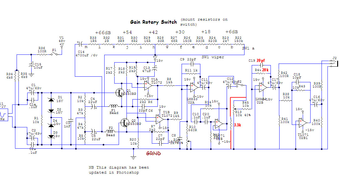
1st. (loosing fader function) put a 3K3 between ccw end of faderpot R13 and gnd, and change the feedback resistor R44 of the following stage from 10K to 20K. Exchange the cap C19 for lead compensation from 10pF to 39pF. This way the previous fader becomes your +/-6dB gaintrim.
2nd. (not loosing the fader function) exchange the 10K resistors R44 and R45 with 100K, get an additional 4K7 lin pot with wiper connected to the inverting input, pots cw and ccw end connect to 2 additional 4K4 resistors. The other side of the 4K4 resistor at the cw extreme connecting to the R13/R45 junction, the other side of the 4K4 resistor at the ccw extreme connected to the R44/C17 junction. Exchange the cap C19 for lead compensation from 10pF to 100pF. Something like this schemosniplet
good luck
-Harpo
for the amek9098 alike, two ways to get there:
1st. (probably easiest/affordable/sourcable) debalancer at unity gain, followed by an inverting variable gain stage with voltage gain varying between 0.5 and 2, might/should be followed by a transformer- or other driver for beefy/balanced out if needed.
2nd. (expensive) two non inverting gain stages with voltage gain of 2 each to get your +12dB on top and a balanced variable -12dB H-Pad in between.
For the green (at least this is the 'All things Green Pre', not an amek, Supergreen or whatever thread) two ways to get there:
1st. (loosing fader function) put a 3K3 between ccw end of faderpot R13 and gnd, and change the feedback resistor R44 of the following stage from 10K to 20K. Exchange the cap C19 for lead compensation from 10pF to 39pF. This way the previous fader becomes your +/-6dB gaintrim.
2nd. (not loosing the fader function) exchange the 10K resistors R44 and R45 with 100K, get an additional 4K7 lin pot with wiper connected to the inverting input, pots cw and ccw end connect to 2 additional 4K4 resistors. The other side of the 4K4 resistor at the cw extreme connecting to the R13/R45 junction, the other side of the 4K4 resistor at the ccw extreme connected to the R44/C17 junction. Exchange the cap C19 for lead compensation from 10pF to 100pF. Something like this schemosniplet
good luck
-Harpo
mathflan
Well-known member
Thanks a lot harpo !
I tried the First method on my green pre, I don't think I did the right things :
This is what I done :
With these mods, the gain trim change Input gain or Output gain?
Thanks
I tried the First method on my green pre, I don't think I did the right things :
This is what I done :
With these mods, the gain trim change Input gain or Output gain?
Thanks
Harpo
Well-known member
With this mod you add +6dB by doubling R44 from 10K to 20K. The voltage gain of this inverting opamp U2B now increases to 2 (Av=R44/R45). To get your +/-6dB request you need to limit the fader function for a max. -12dB loss. This -12dB is a K-factor of 10^(12/20)=0.2512. The faderpot (this is a voltage divider) has a fixed total value of 10K, so you will have to add a resistor at the ccw end of this pot to make the variable range smaller. The needed Rx to get this 0.2512 is Rx/(Rx+R13). With a little algebra you come up with the value of 3354.5 ohm. A 3K3 is the next available standard value. (there are some other ways to get to your +/-6dB request)
The 3K3 in your drawing is in parallel to the faderpot, only loading the previous stage. The ccw end of the faderpot is on its opposite side. Try it this way.
The 3K3 in your drawing is in parallel to the faderpot, only loading the previous stage. The ccw end of the faderpot is on its opposite side. Try it this way.
mathflan
Well-known member
I Corrected my bad wiring on the 3k3 resistors.
It's working, but In fact the "new" +/- 6dB trimmer only change Output stage gain.
There is no solution to have a fine setup to the previous stage?
Is the +/- 6db gain on portico and other Neve designs takes place at the first, second or at the output stage?
Thanks
It's working, but In fact the "new" +/- 6dB trimmer only change Output stage gain.
There is no solution to have a fine setup to the previous stage?
Is the +/- 6db gain on portico and other Neve designs takes place at the first, second or at the output stage?
Thanks
Harpo
Well-known member
Without messing up CMRR and affordable, no.mathflan said:There is no solution to have a fine setup to the previous stage?
Is the +/- 6db gain on portico and other Neve designs takes place at the first, second or at the output stage?
From your above posted part of 9098 schematic this is happening in the not shown part, beginning next to R22 and R25, similar to my sniplett for 2nd option, described above. Dunno about porticos internals.
pjgonzales
Member
- Joined
- Feb 25, 2009
- Messages
- 5
Does anyone have a template for the spacing of holes punched in the front and back panels. I was sweating over having to measure everything precisely myself, but I was told by a friend that people have templates drawn for the panel holes. Can anyone help?? Thanks.
-Peter G
-Peter G
Similar threads
- Replies
- 1
- Views
- 378
- Replies
- 57
- Views
- 5K