G
Guest
Guest
Questions/suggestions/objections?

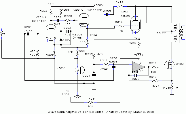
It's a PP amp with triode SE signature where one shoulder is a triode, another shoulder is a controlled current source. It allows to use better transformer (no need for massive iron with gap so no need for an extra copper) and twice more of power from one triode.
As you know a dynamic resistance of a current source is very high so transfer function is determined by a triode only that works in a privileged mode, i.e. less plate current variations.
V102 -- power triode,
A1 & Q103 -- controlled current source,
V101 -- driver for a power triode, also a phase splitter. Triode control signal goes from anode, VCCS control signal goes from cathode, to the same cathode goes positive feedback by current and negative feedback by voltage.
Q101 -- source follower to drive a grid positively,
Q102 -- bias regulator for the output triode.
Resistors in cathode of V102 and in source of Q103 are equal so DC currents through them are equal. Because of time constant of R113 and C103 currents are balanced by average value. However, it introduces some transients, but anyway SE amp is prone to them.
Plus some positive feedback by current will go through C103 to cathode of the 1'st tube, but it may be made very small if to use an opamp with small input currents and increase R113 value in respect to R103.
This idea is result of my previous success with "Tower" amplifiers where I used SS output stage (a voltage follower loaded on a variable current source). They sound very pristine. Alligator is the way to implement similar trick in order to get a SE triode signature.
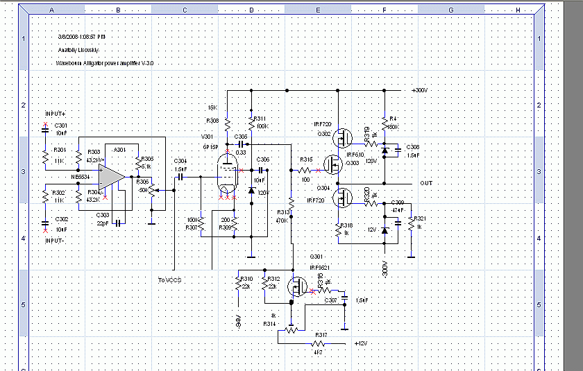
Here is a very simplified version, just to show the concept:


