You are using an out of date browser. It may not display this or other websites correctly.
You should upgrade or use an alternative browser.
You should upgrade or use an alternative browser.
altec 436 rectifier replacement
- Thread starter QUEEF BAG
- Start date


Help Support GroupDIY Audio Forum:
This site may earn a commission from merchant affiliate
links, including eBay, Amazon, and others.
ab0mber
Member
- Joined
- Jan 22, 2013
- Messages
- 14
I am sorry to be 100 questions.
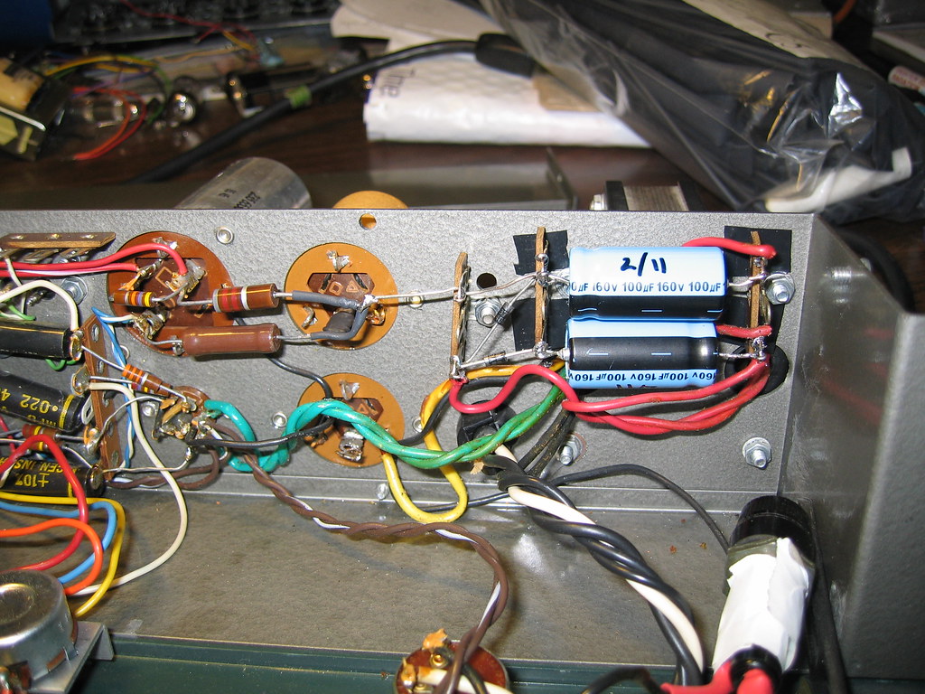
1. are the old caps (smaller ones) being used at all?
2. It's hard to see what is going on by the red wire going under the cap on the right. Is there a schematic for this. Even a quick drawing will help.
Thanks for all this help emrr
1. are the old caps (smaller ones) being used at all?
2. It's hard to see what is going on by the red wire going under the cap on the right. Is there a schematic for this. Even a quick drawing will help.
Thanks for all this help emrr
Mike Cleaver
Well-known member
Looks as if the can caps are disconnected, replaced by the ones with the dates on them.
Lots of people leave the disconnected old cans and selenium rectifiers on the chassis to give the piece an authentic look.
It's always great to date parts you replace and keep notes on your mods on file.
Lots of people leave the disconnected old cans and selenium rectifiers on the chassis to give the piece an authentic look.
It's always great to date parts you replace and keep notes on your mods on file.


MagnetoSound
Well-known member
emrr said:Don't you love that batch of axial caps with the useless polarity marking? That sure helps when they put the radial cap shrink on the axial caps, doesn't it?
Damn! I knew they looked weird, but couldn't put my finger on it! ;D
It's a bipolar! ;D
ab0mber
Member
- Joined
- Jan 22, 2013
- Messages
- 14
Alright guys, I am not out of the woods yet and I appreciate the help thus far. As you can see in the pic on the 436c I replaced both of my leaking caps with some Sprague cans I found ebay. I replaced the Selenium Rectifier with 2 diodes and I fired it up with out any tubes in it to check the voltages of the power supply first.
I immediately noticed that they were like 100 volts under so I immediately thought I am not getting the other side of the wave and the transformer was warmer than i liked. Ugh
So I disconnected the transformer( I thought I fried it) to test secondary output and I got the correct voltage (around 137 volts). transformer is good but is seems that for whatever reason i am not rectifying the 2nd half of the wave. Is there something wrong here anyone can see that might be the reason for the voltage doubler to not be working correctly? All help is appreciated.
Top cap is the 80mfd
bottom is a 80-10-40 mfd
Attachments

ab0mber
Member
- Joined
- Jan 22, 2013
- Messages
- 14
emrr Could you please give me a schematic of what is going on in this. I want to be sure i got it right because it is hard for me to see what is going on in the right hand side of the pic. (the right of the blue caps)
Thanks
Thanks
emrr said:438 rectifier replacement and partial recap
ab0mber
Member
- Joined
- Jan 22, 2013
- Messages
- 14
Alright so I know that I did this correctly and I am starting to think the power transformer is failing under load. Does this sound right to any guru's out there.
I wired it up the same as seen in the above pic. I am only getting 191vdc output of the voltage doubler circuit when it should be around 280vdc. The PT is testing good (137vac) when not under load so I am starting to wonder is it possible that the PT is bad or am I missing something completely obvious that is preventing the double circuit from working correctly?
Thanks
Adam
MagnetoSound
Well-known member
Is the AC voltage dropping excessively under load?
PT damage is possible; I would think a bad cap or wiring error more likely.
PT damage is possible; I would think a bad cap or wiring error more likely.
Similar threads
- Replies
- 21
- Views
- 977
- Replies
- 64
- Views
- 9K