You are using an out of date browser. It may not display this or other websites correctly.
You should upgrade or use an alternative browser.
You should upgrade or use an alternative browser.
"Another Poor Man's" Fairchild 660/670
- Thread starter rotheu
- Start date


Help Support GroupDIY Audio Forum:
This site may earn a commission from merchant affiliate
links, including eBay, Amazon, and others.
Matthew Jacobs i dont think that switch will work.
We need 6 decks 1 pole and that switch is 3 decks 2 pole.
Somewhere on these pages are all the parts needed to assemble the switch that we need.
Great find Kambo.
We need 6 decks 1 pole and that switch is 3 decks 2 pole.
Somewhere on these pages are all the parts needed to assemble the switch that we need.
Great find Kambo.
pyjaman
Well-known member
rotheu said:Network version with 6 deck 6 terminal release switch. This must work, but is expensive, unless you find some surplus cheaper switches.

Hello, everyone!
I've been thinking of an alternative with (possibly) continuous release control :

Of course, the 1M pot can be a stepped control with any stepps you choose.
only 3 poles x 6 positions needed for attack and 1 pot or 1pole x whatever-you-want for release.
EDIT: IT WILL ONLY SEMI WORK. THE COARSE OF THE POT WON'T GIVE THE SAME RELEASE VALUES AT THE SAME SPOTS BETWEEN MAX AND MIN RELEASE for each attack setting...
Laurent.
pyjaman
Well-known member
And for those who find the two last positions useless, a 3x4 lorlin could do the trick...
Laurent.
Laurent.
MeToo2
Well-known member
Here's my 2 eurocent worth about the timing chain discussion after having thought it through for myself.
My reasoning for starting building this variable mu valve compressor was:
1) I was fascinated about the circuit and how it worked
2) i wanted to get hold of something vaguely similar to something that was legendary
3) the original is almost impossible to buy for any price
4) it'll look pretty impressive once finished (22 valves & 8 transformers for dual mono!)
5) it is pretty much impossible to build a copy of the original (availability of transformers and valves etc.)
6) even an indirect copy would cost a fortune to run (e.g. 6386 replacement and balancing)
I think Rotheu has come up with a pretty good compromise here using modern components in a very similar circuit topology.
As previously pointed out you could also customize the timing yourself without getting too radical just by switching in a few fixed CR combinations: it would be simple enough to replace the 2*6 switch of the original with a 2*12 switch (not too expensive, and available in Europe e.g. http://parts.digikey.de/1/1/290888-switch-rotary-dp-12pos-enclosed-c4d0212n-a.html).
That would give you the 6 original settings, plus 6 custom settings of your personal favourite timing parameters.
Isn't that enough?
Aren't you running the risk of trying to get this box to do something it just wasn't designed to do originally and then losing any chance of any magic? It never was that fast a compressor to start with. Shouldn't you be looking to another base design for this sort of functionality e.g. GSSL. One thing about the GSSL is that you need like 4 daughter cards to try and get it to do everything (super side chain, turbo, dual turbo, dual Super side chain dual turbo.) Whereas really just the "Oxford mode" gets you closest to the spirit of the inspiration (the console compressor). Case of creeping features.
So I have decided to implement the original timing chain with a simple 2*6 switch and CR values as near to the original as is easily attainable with new components (e.g. 3.9uF instead of 4uF). I'm using different valves (as previously posted) and I'm also going to try a few tweaks like different transformer ratios (I believe closer to the original) which I'll report back on. One day I might change out the 2*6 for a 2*12. I'm finding that the timing chain is actually physically quite big because I am using cross caps, and despite buying the largest Hammond box things are turning out to be quite crowded. The front panel is also in danger of getting over-crowded with knobs and switches. Adding more stuff would only make that problem worse. Only thing holding me back on my build at the moment is that I'm still waiting for my transformers to arrive from the US. Once its running I'll post pics, mods etc.


![Soldering Iron Kit, 120W LED Digital Advanced Solder Iron Soldering Gun kit, 110V Welding Tools, Smart Temperature Control [356℉-932℉], Extra 5pcs Tips, Auto Sleep, Temp Calibration, Orange](https://m.media-amazon.com/images/I/51sFKu9SdeL._SL500_.jpg)


MeToo2
Well-known member
So my transformers have arrived and I've built the control amp.
I'm OK with calculating the release times: it's a simple RC circuit.
But what about the attack time?
I've been scratching my head and can't figure out how to achieve an attack time of just 0.2mSec specified as per the original without melting the ECC99's or the PSU. In Rotheus diagram with 300V on the plate and a cathode resistor of 220 ohms they will be running very hot. More than their 5W spec at least. I've turned down the plate voltage to about 255V and have a 20mA bias current for testing which limits them to around 5W each half of the ECC99, which is their specification for max dissipation.
Anyone know how this attack time is specified? I know every manufacturer uses a different method.
And equally, does anyone know how to calculate it based on the circuit? It seems to me that all standard plate curves go out of the window. The transient isn't exactly a standard signal. And the amp will encounter an extremely non-linear load: below threshold the diodes won't conduct at all and the amp will just see 3900 reflected via the 10K:600 transformer = 65K, so there'll be virtually no current in the load under normal circumstances. But above the threshold the control amp is basically going to see a pure capacitive load of 2uF to ground that you need to charge to around 30-50V within 0.2mS. Since Q=IT & Q=CV => I=C dV/dT = C*slew rate, so that needs an instantaneous current of around half an amp for 0.2mS. Even with a 4.08:1 transformer that's still 125mA at 250 V instantaneous per channel.
Is it a simple slew rate calculation based on rp at the bias point? I don't think so because the grid will be driven basically to 0V or beyond instantaneously by any large transient. Which leaves Vplate at 250V and Vg @0 so there's going to be an awful lot of instantaneous current in the push side tube. At the same time the partner tube in the pull side will basically switch off with a Vg of -20V leading to a fly back voltage on the transformer also of around 240V giving approx 480V across the transformer. At a ratio of 4:1 that's 120V charging the capacitor. Or will it be current limited? And if so wouldn't it be better to bias at more quiescent current and a lower plate voltage (to keep the wattage the same but increase current drive) e.g. Vplate 250V@20mA or 200V@25mA or 150V@33mA or 125V and 40mA quiescent?
If I had a storage scope now would be the time to capture that transient and see what is happening as the control voltage capacitor charges.
Which makes me wonder 1) how to calculate the instantaneous current drive of the amp (especially because of the feedback loop) 2) is there any advantage to having a large class A standing current in the control amp if it is really just handling a single transient in one direction which then will feedback via the signal amp and kill the input almost immediately? Won't quite heavily biased AB be just as good? 3) how the PSU instantaneous current drive affects the charging process. I'm assuming that if you've got a 100uF capacitor in the PSU charged to 250V DC, that's going to have plenty of charge to get a 2uF capacitor to 50V pretty quickly.
Any comments appreciated.
lewilson
Well-known member
- Joined
- Aug 9, 2005
- Messages
- 218
Good question, I think you need that storage scope. I've been looking for one, but they seem expensive.
I will say that my comp is still working and it is my "go to comp, and I have a lot of nice comps here. Its fast, and the russian tubes work nice. It does have a real fairchilds side chain though.

I will say that my comp is still working and it is my "go to comp, and I have a lot of nice comps here. Its fast, and the russian tubes work nice. It does have a real fairchilds side chain though.
MeToo2
Well-known member
Basic storage scopes aren't that expensive but good ones that can display reasonably high resolution and handle high voltage certainly are. Guess I'm being a bit lazy hoping that someone else had done the hard work for me. It should be pretty straightforward to set up a short release time constant of say 20mS with a 10K resistor in parallel to a 2uF for test purposes and then feed in a low frequency square wave of maybe 10-20 Hz and use that to trigger a normal scope to see if I can get rise time measurements that way. Then I can vary plate voltage and quiescent current to see the effect that has on the charging.lewilson said:Good question, I think you need that storage scope. I've been looking for one, but they seem expensive.
I will say that my comp is still working and it is my "go to comp, and I have a lot of nice comps here. Its fast, and the russian tubes work nice. It does have a real fairchilds side chain though.
jdbakker
Well-known member
MeToo2 said:If I had a storage scope now would be the time to capture that transient and see what is happening as the control voltage capacitor charges.
0.2ms is 18-19 samples at 96ksps.
Get a cheap (external) sound card, optionally mod it for DC input, add some protection diodes and DIY a simple input buffer/attenuator.
JDB.
MeToo2
Well-known member
That'd work but I'm not too happy about connecting experimental valve circuits up to my computer: even with an attenuator and protection diodes. It's my humble experience that some expensive component will heroically fail in order to save a protection diode. I went the oscilloscope way: fed in a low frequency square wave or sawtooth, reduced the release time with a 10K resistor and then triggered on the input via channel 2. Worked surprisingly well.jdbakker said:MeToo2 said:If I had a storage scope now would be the time to capture that transient and see what is happening as the control voltage capacitor charges.
0.2ms is 18-19 samples at 96ksps.
Get a cheap (external) sound card, optionally mod it for DC input, add some protection diodes and DIY a simple input buffer/attenuator.
JDB.
Since there's no definition of the attack time, I invented my own. I measured the time for the control amp to slew to -40V. It's an arbitrary value. But well down the cut off curve of a 6k4p or 6386. I also measured Vcontrol_max before it started releasing.
All of the curves seemed surprisingly similar in shape. A fairly sharp near vertical initial charge followed by a rounding off, and then a classic CR discharge. I think everything was working as it should, but comments are appreciated as always.
I measured the supply voltage, the voltage at the top of the plate of the ECC99, the voltage at the cathode of the ECC99 and the output of the timing chain (2uF in parallel with a 10K). From that I could calculate the other values.
Here's the results.
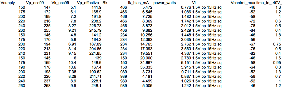
The conclusion I draw from this is that the behavior of the control amp is extremely non linear (as I kind of expected). There is a link between supply voltage, quiescent current, and the attack time and maximum control voltage, but it isn't straightforward at all. Upping the voltage has a positive effect but at the expense of rapidly increasing the power dissipation for very little gain in timing beyond 220V. Upping the current does have a very significant effect up to a certain point (around 10-15mA) but then does not seem to have any significant effect at all beyond that point except again to increase power dissipation for zero gain. Dropping the current to 5mA to attempt to accommodate more power supply voltage limits the max control voltage significantly.
I've decided that the optimum for my set up will probably be Rk of around 220-300 Ohms, which is what Rotheu had in his original circuit, with a regulated power supply of 240-250V shared with the ecc82 & ecc83. That voltage is quite different from Rotheu , as it is a significantly lower voltage (240V versus 300V fro the ecc99), leading to lower power consumption (and hopefully longer tube and power supply life). To be completely fair, I don't know what performance Rotheu achieved so it is difficult to compare figures directly.
I might yet still try feeding the ecc99 straight from the output of the choke inductor as per the original circuit. I believe that this should be fairly smooth and not so current limited as my regulated supply.
Edit: tried rejigging the power supply yet again, connecting the ecc99 to +300V DC (powered via passive CLC filter of 2*100uF & 10H inductor: no active regulation), feeding ecc82 & ecc83 with regulated 240V and and increased Rk to 470 ohms on the ecc99. Worked an absolute treat. Time to -40V = 0.2mSec (approx as per 660 spec). Time to -60V around 0.3mSec and producing max control voltage of -78v after just 1mSec. All with a quiescent current of around 12mA per tube half that's around 3.5W per side.
Hope this at least stimulates others to investigate further, and it's obviously well worth tinkering with this in your build.
KrIVIUM2323
Well-known member
Congratulations Metoo2!
Which kind of transfo did you use finally? 10k/600 or 10K/150?
And B+ for 6k4P? 240V as specified by Rotheu with 6BA6?
Which kind of transfo did you use finally? 10k/600 or 10K/150?
And B+ for 6k4P? 240V as specified by Rotheu with 6BA6?
MeToo2
Well-known member
Rotheu's original design is stable and I'm sure it works. I am currently looking at using Edcor XSM50K/600 and XSM600/50K transformers in the signal amp. I ordered them as a special from Edcor. Because I paid for the one off design charge other people should be able to buy it for the "normal" price. I also intend to test the XSM10K/600 and XSM600/10K in the signal amp and possibly other combinations if I have time. Control amp uses XSM10K/600 and XSM600/10K. B+ on the 6k4P currently set to 150V. That gives loads of headroom so far and I haven't got it to clip yet. I might back it off a bit to say 125V. Could be out of contact for a while though as I have some new work that is taking away my play time.KrIVIUM2323 said:Congratulations Metoo2!
Which kind of transfo did you use finally? 10k/600 or 10K/150?
And B+ for 6k4P? 240V as specified by Rotheu with 6BA6?
[edit] OK it was a rainy Saturday & Sunday here, so I built the second signal amp channel with XSM600/10K (in) and XSM10K/600 (out). The first channel was XSM600/50K (in) & XSM50K/600 (out)
Also looked at the combination XSM600/50K (in) and XSM10K/600 (out) and XSM10K/600 (in) with XSM600/50K (out).
I think I'm done tweaking for now.
I've come to the conclusion that the 50K output transformer does indeed make a difference on the output (at least on my build.)
I've also come to the perhaps surprising conclusion that it's going to be better to reduce gain in the compressor rather than add it. That means a 600/10K input transformer. My reasoning is that if I want to use this on the mix bus or on pre-tracked signals then I don't need 12dB of gain and it is better to allow a higher input signal in for the same output so that relatively speaking the noise floor drops. That means the upstream component would have to provide more gain so it's maybe just shifting a problem around. Anyway, there's nothing for free in valve circuits so you may come to a different compromise for your build. The alternative transformers only cost around $13 so you can play with these combinations yourself without breaking the bank.
So to summarise the tweaks I've made to Rotheu's design for my build (and ALL due credit to Rotheu of course, because I tried a lot of tweaks and many of my bright ideas actually made things much worse compared to his design)
1) built a dual mono version with original 660 timing chain - changed capacitor values to modern equivalents e.g. 4uF ->3.9uF 20uF ->22uF 2uF -> 2*1uF
2) Used 8 * 6k4p-ev tubes per channel. Important to get the higher quality EV (or EB in Cyrillic) version.
I manually matched these on a simple test set up (bought 30 and got 2 channels of 4 pairs of 2 tubes = 16 tubes in use in signal amp)
pin 1 is grid 1
pin 2 is grid 3 (suppressor + shield) which I hard wired to pin 7
(on my 6k4p-ev tubes this is actually hard wired internally within the tube but I don't think that's the case on the 6ba6 for example)
pin 3 & 4 are the heaters.
I used 6.3V AC heaters with 2 * 180 ohm to ground to simulate a centre tap. You could of course use DC heaters if you can build a 4.8 amp supply
pin 5 is anode (via output transformer to 125V)
pin 6 is screen grid.
Connected to pin 5 via 10K screen grid stopper PER tube soldered directly on the socket.
It worked for me. You might want to tweak this.
pin 7 is cathode
3) B+ on the 6k4P set to 125V. B+ on ECC99 300V. B+ on 12ax7 & a12au7 245V
Quiescent cathode voltages: ECC99 around 10-11V. Similar for 6k4p around 9-10V.
The signal amp balanced well with the pot in the middle and without any tweaking (guess the tubes were well matched as I selected them as 4 matched pairs per channel)
4) Changed signal amp transformers to XSM600/10K & XMS50K/600. Due to this choice, the gain drops right down to around 7dB but I believe that the effective signal to noise ratio improves because you can drive the input harder (which I thought to be more inportant). So maybe more like a 670 than a 660.
5) Changed cathode resistor for ECC99 to 470 ohm. You could probably get away with lower but I didn't see any benefit
6) wired anode of 12au7 and 12ax7 to regulated 245V rather than to the ECC99 via a dropper resistor
7) wired up the output transformer so that the whole things was non-inverting
8 ) wired ECC99 unregulated to 300V (stabilized via 12H choke).
9 ) I still have to wire up the VU meters but I'm going to have them switched so that you can also measure the output signal as well as the gain reduction. See no point in measuring the balance myself. I find it easier to do that with an external voltmeter or a scope.
10) for the power supply I used two transformers & two supplies.
Transformers were the T30 model from analoguemetric, connected to an off the shelf Variable HV BJT Power Supply also from analoguemetric containing 2* 100uF 450V aerovox capacitors, plus two 12H Hammond chokes (193b) on each HT power supply. The variable supply also provided 2*12.6V for the heaters for the control amp..
So in total:
2* 2 * 6.3V AC @ 1.2A to power 4 6k4p each winding = 4.8A total for 2 transformers
1* 220V ac 100mA (for 300V on the ECC99 via the choke and regulated to 245V for control amp of a few mA)
1 * 200V ac 100mA (regulated to 125V DC on the 6k4p of the signal amps)
I should also mention that Tube-Town in Germany and Edcor (USA) also gave me great customer service on this project.
Is it a real 660 or 670?
No of course it isn't. But it does seem to act something like a variable mu compressor should and with vaguely similar specs
")
MeToo2
Well-known member
Links to photos.syn said:Great! Upload the photos when you have some free time, please.
http://i958.photobucket.com/albums/ae69/MeToo2_Prodigy/DSC00609.jpg
http://i958.photobucket.com/albums/ae69/MeToo2_Prodigy/DSC00611.jpg
http://i958.photobucket.com/albums/ae69/MeToo2_Prodigy/DSC00612.jpg
http://i958.photobucket.com/albums/ae69/MeToo2_Prodigy/DSC00614.jpg
I have a lot more pictures detailing the build if there's interest.
Some things I did OK and others I messed up. Every one of these is probably unique and something of a prototype
KrIVIUM2323
Well-known member
Great! I'm interested!
Thank you Metoo2!
Look a bit messy in it but there is a lot of things inside that box! ;D
Really a good work! And thank again sharing with us!
Thank you Metoo2!
Look a bit messy in it but there is a lot of things inside that box!
;DReally a good work! And thank again sharing with us!
MeToo2
Well-known member
There's method in the madness I promise. One of the things I did wrong was underestimate the sheer scale of this thing, especially the amount of stuff physically around the control amps. This is actually the biggest box of this style that I could get hold of that Hammond make (Steel 1431+1441+1451-30bk3 series 17*10*4). I basically decided on a 2-660 build because of the power supply I used. It would seem a waste to have all of that complexity for one channel. But I could understand people going for a mono version to reduce clutter and doing the power supply differently.KrIVIUM2323 said:Look a bit messy in it but there is a lot of things inside that box!
Really a good work! And thank again sharing with us!
lewilson
Well-known member
- Joined
- Aug 9, 2005
- Messages
- 218
I did in mine to. I ended up putting the bias supply in a seperate box as well as the timing/ recifier network in another. There attached by an ambilicals and multi pin connectors. It worked out well
and allowed me save my prototype as well as learn.
and allowed me save my prototype as well as learn.
MeToo2
Well-known member
I think I posted earlier.syn said:Great.Don't have the time at the moment to read through your previous posts, but will later.
I'm intrested to see what route did you take PSU wise (at the quick glance it looks like 2 PSUs in one box).
Thanks.
If not: The power requirements for 2 channels are pretty heavy. I couldn't find a single off-the-shelf transformer that would do everything.
That leaves either the choice of going for a custom wound transformer (certainly possible) or building two power supplies that cross-supply the two channels of signal and control amps. You can split this via HT & heaters or other combinations. You could also pair up the 6k4p heaters to be fed by 12.6V DC to decrease current, but the wattage obviously remains the same.
So PSU one does:
300V DC 100mA regulated by 100uF + 12H choke + 100uF (choke #1 is not visible on the photo as it is mounted in the cover!)
that feeds the anodes of the ECC99's on both of the control amp channel #1 & channel #2
+ regulation of 300V down to 240V @ approx 20mA probably peaking higher
that feeds the anodes of the 12ax7 & 12au7 on both of the control amp channel #1 & channel #2
plus 1*12.6V DC regulated @ 700mA to supply heaters of control amp #1 ECC99 + 12ax7 + 12au7
plus 2 * 6.3V AC @ 1.2 amps each to feed 8 * heaters of 6k4p for one signal amp channel #1
PSU two does:
100mA @ ~200V DC regulated by 100uF + 12H choke + 100uF (choke #2 is not visible on the photo as it is mounted in the cover!)
+ regulation of 200V down to 125V DC variable @ approx 60mA peaking higher
that feeds 2*8*6k4p anodes on both signal amps channel #1 & channel #2
plus 1*12.6V DC regulated @ 700mA to supply heaters of control amp #2 ECC99 + 12ax7 + 12au7
plus 2 * 6.3V AC @ 1.2 amps each to feed 8 * heaters of 6k4p for one signal amp channel #2
There's definitely other options, like supplying the heaters separate from the HT, but I always ended up needing two transformers, so this seemed like the cheapest option (HT supplies combined with 12.6V heater supplies were ready designed kits with all components.)
Here's some of the method behind the madness.
I spent a lot of time looking at this physical layout of point to point wiring and this was the only way I could get everything to fit and still have things reasonably accessible during the build, whilst keeping all low signal levels and high impedance connections to controls (front row) away from high amplified levels (mid row) and power supply switching (very back row). Left and right columns are the signal amps. The middle two columns are the control amps. The daughter tag board mounted on the front panel (with all the cross caps) is the timing chain. I drilled almost all of the holes in the chassis before mounting anything (there's probably >>100 holes to drill).
The mass of yellow wires is star grounding to a single point next to the rectifiers of the control amp. The blue wires are control level signals (mostly DC). White = grid & inter-tube signal connections. Twisted purple/red = heater (routed close to the chassis and away from other wires). Orange = beware HT! Screened = signal level in and out. Black = cathodes. Twisted black/red = VU meter (not installed yet) Twisted blue/brown = 220V AC etc. All components are mounted as closely to the tube socket pin as possible. It may look like a birds nest but actually bundling up cables nicely and neatly together that carry different signals can make matters far worse due to mutual inductance and capacitance.
I had zero problems with stability or oscillation or phase effects and even just some minor problems with 50Hz noise.
Maybe the best advice I could give is "start with a very big box" :
Similar threads
- Replies
- 3
- Views
- 2K