You are using an out of date browser. It may not display this or other websites correctly.
You should upgrade or use an alternative browser.
You should upgrade or use an alternative browser.
"Another Poor Man's" Fairchild 660/670
- Thread starter rotheu
- Start date


Help Support GroupDIY Audio Forum:
This site may earn a commission from merchant affiliate
links, including eBay, Amazon, and others.
MeToo2, thank you, you are absolutely right, tapping for the HT PSU droped. G9 style PSU is cheep and easy to build, and multiplies of it will save on heat. I'm thinking to add relays to "bleed off" HTs after power off. Also, to extend tube life I'm thinking to add two switches for powering the unit, so I can switch heaters and HT independently.
O.K. then, I'll go AC for the heaters too, if needed, I can regulate later. EdcorXPWR011 is EI, i think that helps keep the noise down. I'm wandering can one expect good results using toroid in the same situation? I used toroids for tube equipment builds before, but every time, regulated and well filtered.
Thank you.lewilson said:I used a edcore XPWR011 for a single channel 660 type comp. Unregulated 6.3vac works fine in mine, Its very very quiet.
O.K. then, I'll go AC for the heaters too, if needed, I can regulate later. EdcorXPWR011 is EI, i think that helps keep the noise down. I'm wandering can one expect good results using toroid in the same situation? I used toroids for tube equipment builds before, but every time, regulated and well filtered.
MeToo2
Well-known member
I think it's fair to say that there's a huge range of opinions on whether heaters should be fed with DC or AC, and which is better. I honestly don't know.syn said:
I've decided to go with two toroids with multiple taps and a pair of off-the-shelf adjustable b+ power supplies (one for the signal amp and one for the side chain amp), so I can easily experiment with the plate voltages without having excessive power drop across the regulators. The 240V specified for the 12ax7 will only be a couple of mA so that's easily derived from the 300V regulated supply either via a CR arrangement or an additional regulator daisy chained on like you suggested inn the diagram you posted. I can always use these components in another project if it doesn't work out.
I'm concerned about running the plates on a 6k4p so hot as the 6386 on the real 660. They both have a limit of 300V max plate voltage. Driving the plate with 240V suggests that it can easily reach 480V when driven hard due to class A and auto-transforming on the output transformer. Although the current will be not be huge at this point (especially with my choice of the 50K:600 ohm output transformer) I'm still concerned about breakdown. I just don't know why the max plate voltage is specified that way, whether the limit is power or voltage related. I'm guessing by the shape of the max power curve for screen dissipation on the 6ba6 data sheet that it may be a combination of the two (both power and voltage limits), so I want to start out conservatively.
One side benefit is that the associated off-the-shelf power supply can provide a regulated 12.6V DC at 1A for the side chain amp.
So I'm gonna go 12.6V regulated DC heaters for the side chain amp and 6.3V AC heaters for the signal amp, purely for the pragmatic reason that's what the power supply I've bought can do, and it is the cheapest way of getting started without going fully custom on something I'm not sure I can properly specify at this time
") The off-the-shelf supplies were as cheap or even cheaper than buying the individual components myself. One thing I've noticed is that if a component is labeled as 'tube' or 'vintage' or 'custom' it suddenly costs more. I'll let you know if my chosen route works out. Otherwise I can always retro-fit an additional DC heater supply for the signal amp via an additional (cheap) transformer and LM based regulators later.
The off-the-shelf supplies were as cheap or even cheaper than buying the individual components myself. One thing I've noticed is that if a component is labeled as 'tube' or 'vintage' or 'custom' it suddenly costs more. I'll let you know if my chosen route works out. Otherwise I can always retro-fit an additional DC heater supply for the signal amp via an additional (cheap) transformer and LM based regulators later.6386 are known to die early on 660-670, at least many sources on the net say so, above might be the reason, however, I don't know why they are run that high V. Good luck.MeToo2 said:I'm concerned about running the plates on a 6k4p so hot as the 6386 on the real 660. They both have a limit of 300V max plate voltage. Driving the plate with 240V suggests that it can easily reach 480V when driven hard due to class A and auto-transforming on the output transformer.
jdbakker
Well-known member
syn said:
The question then becomes (a) how much your line voltage varies and (b) how much you care about your GR meter zero drifting.
syn said:6386 are known to die early on 660-670, at least many sources on the net say so, above might be the reason, however, I don't know why they are run that high V. Good luck.MeToo2 said:I'm concerned about running the plates on a 6k4p so hot as the 6386 on the real 660. They both have a limit of 300V max plate voltage. Driving the plate with 240V suggests that it can easily reach 480V when driven hard due to class A and auto-transforming on the output transformer.
ISTR that tube dissipation (not peak voltage swing) is highest when idling. Someone (emrr? Larrchild?) proposed an auto-timeout that would lower B+ after a few minutes of no signal.
JD 'squelch' B.


MeToo2
Well-known member
I was using "hot" in a slang sense to mean "high voltage" when referring to 240V, rather than worries about thermal dissipation. Apologies.jdbakker said:ISTR that tube dissipation (not peak voltage swing) is highest when idling. Someone (emrr? Larrchild?) proposed an auto-timeout that would lower B+ after a few minutes of no signal.
JD 'squelch' B.
My calculations predict that the dissipation will be around 4mA @150V quiescent pate voltage = 0.6W, which is within the limit of just the screen grid on a 6k4p, so that should be really safe (plate can dissipate an additional 3W) 150V will also double to 300V, which is also below the max plate voltage. So that's about where I was intending setting my upper limit for testing of the signal amp, and starting my test at around 100-125V and seeing how that responded.
What really concerns me is the following graph of screen rating for a 6ba6 (a 6k4p is pretty much a 6ba6 clone)
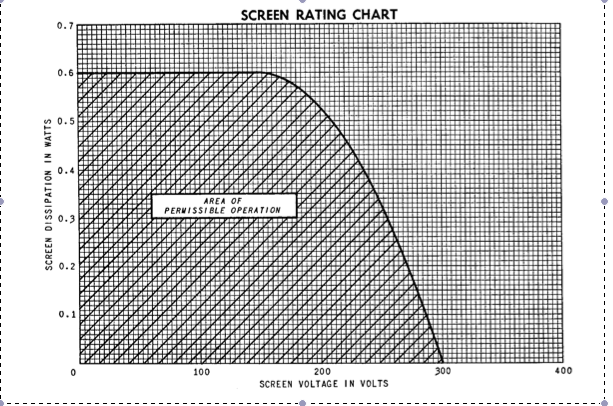
This does suggest to me this is where the limit of 125V for screen grid comes from. I have no idea of the underlying physical mechanism of where this curve comes from.
But it also basically says to me that you cannot take any power out of the screen grid above a screen grid voltage of 300V, which is why I think 240V quiescent may well be a potential problem in push pull triode mode (which will generate around 480V on the plate & screen grid at the peak of the cycle).
rotheu said:Timing network with independent attack and release controls and true stereo linking (two linked networks are isolated and don't affect each other)

Hi
I think this network will not work.
Because if you choose a fast attack slow release, for example, the cv will not only pass the 510k resistor but it will also loop through all the other resistor networks, back to the slow release resistor bus, which will lead to a total resistance much lower than 510k.
Can anybody confirm this or am just a little dense in the moment?
Thanks Tobias
lolo-m
Well-known member
I don't see the point. This network must work.
Did you understood that :
Attack switch is a dual 6 position (upper 2).
Release is a single 6 position (lower 1).
Did you understood that :
Attack switch is a dual 6 position (upper 2).
Release is a single 6 position (lower 1).
Yes I understand that, but have a look. If you send the cv to the fast attack time release resistors and choose 510k to ground, the cv will also go through the 51k resistor of that bulk and into the 5.1k restor of the next bulk of release resistors, than through the 51k resistor back to the slow release bus. And that will happen with all the other resistor bulks, too.
It seems logical to me...
It seems logical to me...
lolo-m
Well-known member
Yes, you're right ;D :-[ ;D. It doesn't work.hop.sing said:Yes I understand that, but have a look. If you send the cv to the fast attack time release resistors and choose 510k to ground, the cv will also go through the 51k resistor of that bulk and into the 5.1k restor of the next bulk of release resistors, than through the 51k resistor back to the slow release bus. And that will happen with all the other resistor bulks, too.
It seems logical to me...
I never give a really long look at this network as I prefer to have a slow/fast switch with a lot less components... I would use 6 different resistors and 6 different caps (even if it's worthless). To slow the attack it's a lot more simple (and effective) to add a serial resistor to fill the cap slowlier.
Well, Rotheu stated that the compression action sounds better with no serial resistor in front of the cap. But he obviously never built this network ??? I heard to, while testing my compressor, that 10uF with no resistance in front sounded better, at least different, than 1uF with resistance added to get the same attack. May the strained sidechain, maybe something else ...
I like options, so I have to think about a working timing network for me, looks difficult.
I like options, so I have to think about a working timing network for me, looks difficult.
Matthew Jacobs
Well-known member
Well I started building this switch and I think it's genius...
Yes, all the resistors are interconnected so the values add up to some crazy 6 dimensional madness.
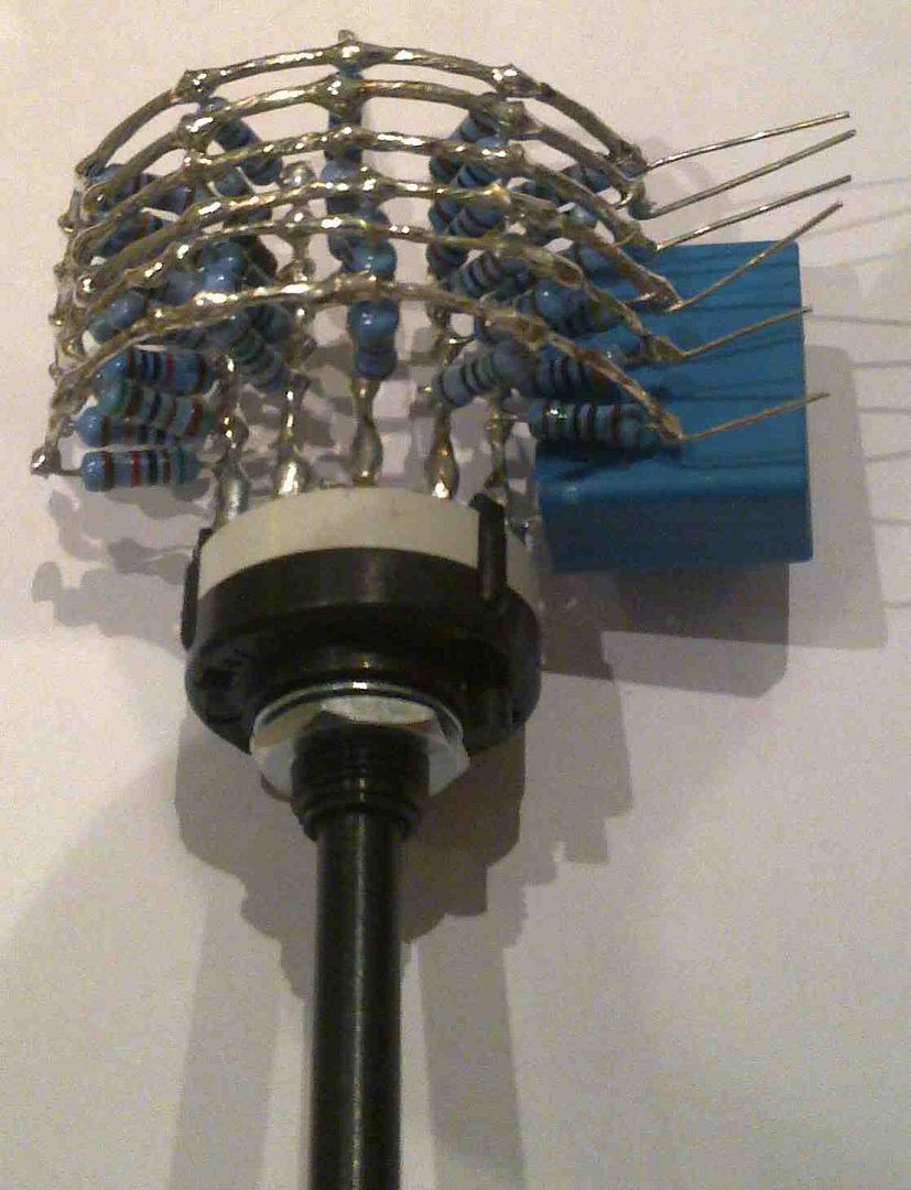
I didn't have time to build the rest of the circuit. Also my knowledge of electronics is limited so maybe if I give you guys the measurements of each pin configuration maybe you could see if it would work.
Attack 1 (1uF):
Release 1 = 21k5
Release 2 = 21k6
Release 3 = 21k7
Release 4 = 21k8
Release 5 = 22k
Release 6 = 22k3
Attack 2 (10uF):
Release 1 = 2k23
Release 2 = 2k32
Release 3 = 2k42
Release 4 = 2k52
Release 5 = 2k71
Release 6 = 3k08
Attack 3 (33uF):
Release 1 = 695R
Release 2 = 789R
Release 3 = 894R
Release 4 = 984R
Release 5 = 1k171
Release 6 = 1k548
Attack 4 (47uF):
Release 1 = 310R
Release 2 = 403R
Release 3 = 506R
Release 4 = 598R
Release 5 = 786R
Release 6 = 1k163
Attack 5 (100uF):
Release 1 = 269R
Release 2 = 362R
Release 3 = 463R
Release 4 = 556R
Release 5 = 744R
Release 6 = 1k123
Attack 6 (330uF):
Release 1 = 119R
Release 2 = 212R
Release 3 = 316R
Release 4 = 410R
Release 5 = 597R
Release 6 = 972R
I think Rutheu build this switch and commented that it worked well. I personally think it will work and once I finish my build (which could take a long.... time) I can test it out.
J
Yes, all the resistors are interconnected so the values add up to some crazy 6 dimensional madness.
I didn't have time to build the rest of the circuit. Also my knowledge of electronics is limited so maybe if I give you guys the measurements of each pin configuration maybe you could see if it would work.
Attack 1 (1uF):
Release 1 = 21k5
Release 2 = 21k6
Release 3 = 21k7
Release 4 = 21k8
Release 5 = 22k
Release 6 = 22k3
Attack 2 (10uF):
Release 1 = 2k23
Release 2 = 2k32
Release 3 = 2k42
Release 4 = 2k52
Release 5 = 2k71
Release 6 = 3k08
Attack 3 (33uF):
Release 1 = 695R
Release 2 = 789R
Release 3 = 894R
Release 4 = 984R
Release 5 = 1k171
Release 6 = 1k548
Attack 4 (47uF):
Release 1 = 310R
Release 2 = 403R
Release 3 = 506R
Release 4 = 598R
Release 5 = 786R
Release 6 = 1k163
Attack 5 (100uF):
Release 1 = 269R
Release 2 = 362R
Release 3 = 463R
Release 4 = 556R
Release 5 = 744R
Release 6 = 1k123
Attack 6 (330uF):
Release 1 = 119R
Release 2 = 212R
Release 3 = 316R
Release 4 = 410R
Release 5 = 597R
Release 6 = 972R
I think Rutheu build this switch and commented that it worked well. I personally think it will work and once I finish my build (which could take a long.... time) I can test it out.
J
lolo-m
Well-known member
The switch gives you an RC network so it'll work... but not as Rotheu thinked it should.
Example:
Attack 1uF + release position 1 will give you a release of approx 22ms (R X C).
Attack 1uF + release position 2 will give you a release of approx 22ms (R X C).
Attack 1uF + release position 3 will give you a release of approx 22ms (R X C).
Attack 1uF + release position 4 will give you a release of approx 22ms (R X C).
Attack 1uF + release position 5 will give you a release of approx 22ms (R X C).
Attack 1uF + release position 6 will give you a release of approx 22ms (R X C).
As the attack is given by the power of the SCamp, you'll have 6 positions with the same attack and release :'(...
But the design can be improved calculating which resistors combination can give 51K to really have 50ms of release time, etc... Huge headache for the calculation!
Example:
Attack 1uF + release position 1 will give you a release of approx 22ms (R X C).
Attack 1uF + release position 2 will give you a release of approx 22ms (R X C).
Attack 1uF + release position 3 will give you a release of approx 22ms (R X C).
Attack 1uF + release position 4 will give you a release of approx 22ms (R X C).
Attack 1uF + release position 5 will give you a release of approx 22ms (R X C).
Attack 1uF + release position 6 will give you a release of approx 22ms (R X C).
As the attack is given by the power of the SCamp, you'll have 6 positions with the same attack and release :'(...
But the design can be improved calculating which resistors combination can give 51K to really have 50ms of release time, etc... Huge headache for the calculation
!Matthew Jacobs
Well-known member
Alright, so the variations in resistance is simply not enough to give the various stated release times. Pity.... :-\ that switch took me ages to solder...
What is the formula for calculating rc times in a sidechain like this one? Isn't this network slightly different cause there is no series resistors?
The attack is set by the cap values right? 1uF = 0.1ms, 10uF = 1ms, etc...
The release is set by the resistors right?
If I know the correct calculations for the attack / release times I could try and work out a excel spreadsheet to give us the correct values for this switch.
J
EDIT:
I think the formula is: (C (uF) x R) / 1000 = t(ms)
lolo-m
Well-known member
You nearly got it !Matthew Jacobs said:I think the formula is: (C (uF) x R) / 1000 = t(ms)
The exact release formula of a Fairchildish RC network is : C (in F) x R (in ohm) = t (in s)
But as you changed the references, the result is the same than yours
!It isn't really true but it's the way Fairchild calculated it so...
Have fun and stop before the headache becomes too hard
!Matthew Jacobs
Well-known member
lolo-m said:Have fun and stop before the headache becomes too hard
LOL....
I think I will stop before I begin... ;D
6 to the power of 6 signal paths through resistors, that means 46,656 calculations
yeah, I now realize how crazy this labyrinth of resistors is.... Some in parallel, some in series... Must be possible to sort out with a computer, but there must be a easier way.... surely there must.....
For example:
1 attack switch and 6 release switches....
Imagine the front panel design.... lolo-m you might like that.... will look good next to your crazy looking GSSL (IIRC). I saw your build photos on the french forum...Or maybe a release switch made up of a gang of 6 stacks...
Or just stick to the original time network...
J
lolo-m
Well-known member
Yes... but you can skip position 5 and 6 and replace them by more acurate simple RC network as they were only usefull to regulate the output program for radio stations...Matthew Jacobs said:Or just stick to the original time network...
If I had to have to choose for a 2 switch system (attack + release) I would simply find the release resistors that give me the fastest attack+release and the slower usable in fast attack/slow release setting. Most of the time when you need a slow attack you need a quite long release... If not, you'd better use another compressor !
Thanks for the GSSL but it is eight 1176 in one box not a GSSL ;D ! Makes me think I should build one...
I am in the same position as you are. What to do? I was just about to solder the crazy thing, when I saw the problem. Now I want a little bit flexibility, a long attack with a variable release and so on.Matthew Jacobs said:lolo-m said:Have fun and stop before the headache becomes too hard
LOL....
I think I will stop before I begin... ;D
6 to the power of 6 signal paths through resistors, that means 46,656 calculations
yeah, I now realize how crazy this labyrinth of resistors is.... Some in parallel, some in series... Must be possible to sort out with a computer, but there must be a easier way.... surely there must.....
For example:
1 attack switch and 6 release switches....
Or maybe a release switch made up of a gang of 6 stacks...
Or just stick to the original time network...
J
My Vari Mu has turned out to be like a little child in the meantime, it grows and grows, makes a lot of work, but is real joy, too.
I started with the prr design and pcc189 tubes, tried out all kinds of make up amps and so on.
Than I found the E.A.R schematics on the net and cloned the very clever solid state sidechain circuit and the biasing circuit, which is basically a fairchild 660 biasing circuit (Not 670, I learned that in this great thread, thanks), paralled two pcc189 per channel into a lundahl LL1660 in 4.5:1 configuration and now I need a timing circuit, that fits my needs.
By the way, what I found out is, that the biasing method with the negative voltage on the balance pot is a huge contributor to the sound of the compression.
With the easy biasing method (Cathode just to ground with resistor and balance pot), you need much less negative control voltage for the same amount of compression, than with the fairchild way. I do not really understand that yet, but I have -12V on the grid where I had -4V before for the same amount of gain reduction and compression sounds definitly different now.
I did not measure the voltages on the cathode during compression, but probably they are moving in the direction of the grid voltages with the current changes (because of the negative supply voltage on the balance pot) so the grid has to go a little further.
Back to the timing network. for now I use a 4,7 uF cap with a 5K attack pot and 100K release pot and it sounds good, maybe I leave it that way. No resistance in front of the cap might sound a little different or better, but I have no idea how to implement that with some kind of flexibility.
Which one exactly and where? Care to share the url or upload to gmail account?hop.sing said:Than I found the E.A.R schematics on the net...
Would be interesting to see a clever sidechain circuit...
Similar threads
- Replies
- 3
- Views
- 2K