You are using an out of date browser. It may not display this or other websites correctly.
You should upgrade or use an alternative browser.
You should upgrade or use an alternative browser.
Another Vari-mu - interstage thread...
- Thread starter Big Bear
- Start date


Help Support GroupDIY Audio Forum:
This site may earn a commission from merchant affiliate
links, including eBay, Amazon, and others.
Well, you could also replace the triodes with NJFET's. I used a pair of 2n3819 into a 5k center-tapped xfmr. Then I got back to my senses and used a VCA. 8)joaquins said:Also I don't see the point to avoid SS stages in a world that is SS... It's nice a tube gain stage, but to avoid OP TX you could use a SS output to get low Z... same for input and you could use a more easy to get IP TX and work at lower Z...
abbey road d enfer said:Well, you could also replace the triodes with NJFET's. I used a pair of 2n3819 into a 5k center-tapped xfmr. Then I got back to my senses and used a VCA. 8)joaquins said:Also I don't see the point to avoid SS stages in a world that is SS... It's nice a tube gain stage, but to avoid OP TX you could use a SS output to get low Z... same for input and you could use a more easy to get IP TX and work at lower Z...
I know what you mean, no offense, it's nice an all tube anything... but not always posible, not in a 500 format compressor for example, my prupose may be possible in 1 500 case.
Would be nice to try out this fet topologie... What I'm trying to take out here if cutting corners for cost or space what I would like is getting the varimu compression characteristics but avoid anything else that takes space or money... Bear was trying to avoid IP TX, and is hard to belive that never again in the life will be something produced without any SS path from the musician's intrument to the lister's ear. I know transformers add some mojo and colour and I love them, but avoid SS is like avoid a wire today, when I was born IC's was already working everywhere, but I've listen some records that never been touched by a single transistor with a vinyl and all tube amp, it's nice, but hard to belive this could happen again (with a new production)
My idea is to use as gain cell the tube and the rest of the signal path as good as the rest of my chain. If someone has or know a studio that record with U67, Summit pre, an Apex tape recorder, pultec eq, altec compressors and go direct to vinil today please let me know I'd love to know it!
JS
> The SS side chain in PRRs compressor looks ideal
No. It is a hasty-hack when I ran out of better ideas.
> why an interstage is used in Vari-Mu designs
At the input, we need a common-mode DC signal with fairly fast rise- (fall-) time imposed on the differential audio signal. We may also want floating input. A transformer does this well. The simplest all-opamp equivalent that I have found uses five opamps, an awkward number.
At the output of the vary-Mu, consider: the tubes idle at HIGH current then must slam to very-low current to reduce gain. If R-C coupled, the plates both go from 40V to 120V very quickly. This tends to knock the next-stage out of operation until the capacitor charge drains. You could instead use a diff-amp with large common-mode range, but this requires a supply voltage larger than the one the vary-Mu is run on. (You can't use the divider trick because the output of the vary-Mu is weak and reducing it will put you closer to universal hiss.) The transformer ignores this large common-mode shift. (Yes, several popular designs do slam the recovery stage. Most are ex-Broadcast limiters, usually economical, where a quick burst of controlled clipping in the limiter recovery amp is acceptable and preferable to clipping in the 50KW transmitter or putting more money in the limiter. Sometimes significant grid resistances to control the momentary overload.)
> you could also replace the triodes with NJFET's
Yes. But Silicon FETs are not tubes. They are rather "better", in ways which are not-so-good for a vary-Mu limiter. (Also matched-pairs have become very rare.)
If FETs have been invented, the FET attenuator side-steps many of the complexities of the vary-Mu, with THD and S/N which can be very acceptable for fine broadcast. I think there are a few (or few-dozen) designs around.
Getting on 20 years to well-matched BJT arrays we have the dBx/THAT VCAs which push the THD/SN envelope far-far wider. The V/dB law means a different sidechain function, though you could just put a log-amp at the VCA CV input and treat it all as "linear". dBx favored staying in log domain, with interesting consequences, but the idea makes my head hurt.
joaquins said:abbey road d enfer said:Well, you could also replace the triodes with NJFET's. I used a pair of 2n3819 into a 5k center-tapped xfmr. Then I got back to my senses and used a VCA. 8)joaquins said:Also I don't see the point to avoid SS stages in a world that is SS... It's nice a tube gain stage, but to avoid OP TX you could use a SS output to get low Z... same for input and you could use a more easy to get IP TX and work at lower Z...
.....Bear was trying to avoid IP tx ..."
JS
I'm sorry if I suggested that, but that is not my goal. I am very happy to use transformers, certainly in, interstage and out.
Maybe the confusion came from me asking whether further interstage transformers are completely necessary after the first stage. The suggestion by PRR was that gain stage would probably be needed, and I asked whether a RC coupled stage would be adequate here..?
Could someone give me details of the side chain transformer that is used a lot? Is it just a lowZ 1:1?
In Analog's (I think) design http://www.twin-x.com/groupdiy/albums/userpics/Mooo.JPG is the transformer simply a phase splitter or is it serving as extra isolation too maybe?
I guess my question is, would I still need one if I were to take a balanced signal to the side chain? And if so, why?
Many thanks
Thanks for all comments so far!
I get that but I didn't say to protect me... just beacuse I belive you where looking and my idea and prupose around it.
In this scheme has an IP TX, a side chain TX and the OP TX, I guess you asked about the last one... It's a push pull output configuration, The varimu stage will need a deeper analysis at least for me... U3/U4 seems to be voltage sources and make U1,2,8,9 working almost at constant voltage and low Z but I can't see much signal comming out off them, I don't know this tubes specs but they are working at low Z.
With a conventional varimu stage U5,6 would see the thumb and change it's gain (anti varimu) Still this thumb wouldn't reach the output because of OP TX.
JS


![Electronics Soldering Iron Kit, [Upgraded] Soldering Iron 110V 90W LCD Digital Portable Soldering Kit 180-480℃(356-896℉), Welding Tool with ON/OFF Switch, Auto-sleep, Thermostatic Design](https://m.media-amazon.com/images/I/41gRDnlyfJS._SL500_.jpg)


Considering it takes the AC plate voltage to provide the rectified DC, I think it's close to unity. The AC plate voltage is not very high, in regard to the low-ish gain of the circuit, and the side-chain DC voltage needs be about 20-30V.Big Bear said:Could someone give me details of the side chain transformer that is used a lot? Is it just a lowZ 1:1?
Quirky design IMO.In Analog's (I think) design http://www.twin-x.com/groupdiy/albums/userpics/Mooo.JPG
The method chosen for avoiding DC thumps is crude. The transconductance tubes are loaded with very low value plate resistors (430 ohms! plus whatever output impedance the cath-follower has - in total about 600-800 ohms), resulting in gain of about 6-8dB.
For the following tubes (in the output stage) the ratio between audio voltage and thump voltage is not better than with higher value resistors; since the audio voltage is lower, the S/N ratio is certainly not better.
I don't see any advantages in this complicated configuration.
If one is ready to use additional tubes, there is a possibility to make a cath-follower behave like an inductor by adding just a few components (see attached). That would improve the resistance to thumps.
Assuming the output xfmr is 1+1:1, each plate in the output stage sees 2.2k, resulting in about 20dB gain. Considering the input voltage is split in half at the grids of the input stage, the overall gain is ca. 22dB.
With a nominal +4dBu at the input, the AC plate voltage at the output stage is ca. 20Vrms, resulting in about 28V after rectification, which is about right.
I don't really understand your question. The xfmr is there to provide push-pull operation AND impedance adaptation. The fact that it also provides galvanic isolation is a welcome bonus.is the transformer simply a phase splitter or is it serving as extra isolation too maybe?
Yes, you would need one, because there is no other usable output for the audio signal, unless you want to redesign the ouput stage for plate resistors and managing the interface with the outside world differently.I guess my question is, would I still need one if I were to take a balanced signal to the side chain? And if so, why?
I think this schemo is to be taken as an unfinished experiment.
Attachments

Think ive lost myself here.
Let's forget about Analog's circuit, I was only showing it for the example of the side chain transformer.
Assuming the output xfmr is 1+1:1, each plate in the output stage sees 2.2k, resulting in about 20dB gain. Considering the input voltage is split in half at the grids of the input stage, the overall gain is ca. 22dB.
I plan on using the LL1689 as an output transformer, which is a 9+9:1.
I think ultimately what I would like to do is use the topology I started with, or similar, but I would really like to use a more sophisticated side chain that I have in the past.
The majority of vari-mu circuits I have built have been very similar to the Altec 436C. http://www.dvq.com/hifi/images/436c.pdf Which simply AC couples taps from the output valve anodes and rectifies this. After reading a lot here and looking at many different designs it is clear that this is not very ideal at all. So I would like to experiment with a few different approaches and am just trying to understand decisions others have made.
Is it reasonable to take a balanced signal from the output valves anodes (similar to the 436C) and buffer this to a lowZ line, then rectify this and process through side chain circuitry to the GR valve grids?
Or maybe it is far easier to tap one anode and buffer, then transformer balance, then rectify..?
The TAB U73 is an interesting circuit, it has a dual output from the IP transformer which is amplified and by a PCF80 with a cathode follower, then transformer balanced.
All different approaches...
I would like to have an agreeable and approved side chain circuit that works well, initially I did not want to have another transformer added, but if a cheap one works that is OK. alternatively if SS circuitry works then that is great too! And if it works then I can put more attention into attack and release circuitry
Thanks
In an era where valves were considered expensive, it could be justified... by bean-counters. Why designers accepted playing this game is somewhat beyond me, except they may have found gratification in squeezing as much functionality as they could from as little hardware they were allowed to put in their products.Big Bear said:The majority of vari-mu circuits I have built have been very similar to the Altec 436C. http://www.dvq.com/hifi/images/436c.pdf Which simply AC couples taps from the output valve anodes and rectifies this.
In view of the common availability of high-voltage FET's, it makes sense.Is it reasonable to take a balanced signal from the output valves anodes (similar to the 436C) and buffer this to a lowZ line, then rectify this and process through side chain circuitry to the GR valve grids?
It's not easier, it's probably not as good, it's more expensive, I wouldn't do that.Or maybe it is far easier to tap one anode and buffer, then transformer balance, then rectify..?
Yes, it's one of a very few non-VCA based feed-forward limiters.The TAB U73 is an interesting circuit, it has a dual output from the IP transformer which is amplified and by a PCF80 with a cathode follower, then transformer balanced.
There are so many ways to skin a cat that I cannot say that I would "approve" a side-chain. The subject has been debated here, you want the SC circuit to deliver a low impedance to the Atk/Rel path without loading too much the audio path, choose the one you feel comfortable with.I would like to have an agreeable and approved side chain circuit that works well, initially I did not want to have another transformer added, but if a cheap one works that is OK. alternatively if SS circuitry works then that is great too!
That's really helpful thank you.
I cut my teeth building these 436C style circuits and was never impressed with the compression, but when working for old boys it can be hard to suggest change / experimentation etc.
Glad I found this site, loads of good info and members. I will stop talking about it and start building it and see how i get on!
Cheers
Bear
PRR already answered that. It takes a high-voltage differential amp; it's not impossible, just complicated.DaveP said:Wouldn't a differential amp like a long tailed pair work instead of an interstage? Very high input Z equals small coupling caps. Presumably the thump would cancel as its common mode?
Great thread BTW 8)
best
DaveP
Yes he did, but it could be a low voltage Vari-mu stage as well and cathode followers can follow very large voltage changes. This probably means a high current triode with a low plate resistor from a low B+ rather than a pentode or pentagrid.................mmmmm
best
DaveP
best
DaveP
This is not the issue. The difficult part is getting rid of the common-mode voltage; it takes a differential amp capable of handling about 100V variation of CM voltage. Not trivial.DaveP said:Yes he did, but it could be a low voltage Vari-mu stage as well and cathode followers can follow very large voltage changes.
> it could be a low voltage Vari-mu stage
That implies low input overload. "Probably" same/similar input hiss voltage. Reduced S/N.
Using traditional tubes at traditional voltages you get about 1-2V input overload and about 1-2uV input hiss: 120dB S/N. BUT for a limiter then you must subtract the amount of gain reduction needed. If overload is harsh, you want ample margin. Say 20dB nominal 30dB stinko.... we are down to 90dB S/N which is not up to the nominal specs of 16-bit audio. True, some tracks hardly need 50dB, but others don't fit in 96dB. I would prefer the limiter not spoil the final S/N. Of course laterly I've used more digital level management, and if I did it more I would be recording 24-bit and massaging down to 15-bit.
> differential amp capable of handling about 100V
I was thinking DaveP was thinking a *real* low voltage. 12V even 24V on the tube would be do-able with simple IC opamps. But overload voltage goes down linear, output current goes down as Child's Law, the output power gets very small, which may become an additional hiss headache.
I must be thick as what you clever guys are saying does not make sense to me.
This is the circuit in my mind,
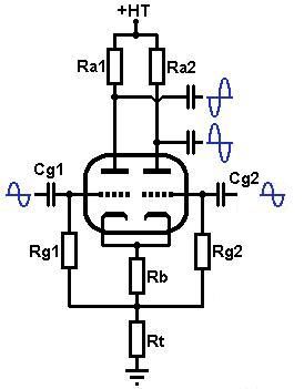
This circuit is usually made with one grid capped to ground, typically 100V difference, so whats the difference?
No pun intended")
The voltage between grid and cathode is constant no matter what, it follows anything.
If the varimu tubes drop any voltage together it makes no odds as its the difference that's amplified.
The input caps are tiny due to the very high input Z, so charge/discharge quickly
best
DaveP
This is the circuit in my mind,

This circuit is usually made with one grid capped to ground, typically 100V difference, so whats the difference?
No pun intended
The voltage between grid and cathode is constant no matter what, it follows anything.
If the varimu tubes drop any voltage together it makes no odds as its the difference that's amplified.
The input caps are tiny due to the very high input Z, so charge/discharge quickly
best
DaveP
Here, we're talking about both grids driven by anti-phase signals coming from the transconductance cell, exactly how it's drawn.DaveP said:I must be thick as what you clever guys are saying does not make sense to me.
This is the circuit in my mind,
This circuit is usually made with one grid capped to ground, typically 100V difference, so whats the difference?
Not entirely. If CM voltage varies, quiescent current varies also.The voltage between grid and cathode is constant no matter what, it follows anything.
That would be in a perfect case of infinite resistance constant current source, which a resistor to ground is not. You could increase the CM rejection by increasing the value of the common cath resistor Rt and tying it to a negative voltage, or even a true CCS. In brief, using standard valve oscilloscope technology.If the varimu tubes drop any voltage together it makes no odds as its the difference that's amplified.
No. CM input Z is very high (as in a Fender amp), but differential input Z is just the grid resistors, no bootstrap there.The input caps are tiny due to the very high input Z, so charge/discharge quickly
So basically you need the standard C-R values like 0.1uF/220k.
Recovery time is about 150msec, during which gain varies by about 6dB.
Agreed, the voltage thump is decreased by about a factor 10. It's still a far cry from the rejection offered by a xfmr.
Bootstrap works when the cathode moves in the same direction as the grid. In the diff amp, the grids move in opposite directions hence the cathode doesn't move.DaveP said:So the antiphase cancels the bootstrap then?
That wouldn't solve any problem. The recovery time is directly dependant on the LF corner frequency; whether it's 0.1uF in 200k grid leaks or 2nF in the 10Meg bootstrapped Z of a cath-follower, the effects are the same.Two bootstrapped Cathode Followers preceeding that stage would help then?
There's the possibility to use this cath-follower as a Sallen & Key filter that would exhibit 2nd or maybe 3rd order response, somewhat shortening the recovery time for a given LF corner frequency, though.
Too complicated IMO, in regard to the fact that simpler solutions exist.
What I was thinking of, was using a low mu 6080 as a direct coupled CF (both halves in push pull) to follow the vari-mu tubes, with both running from a B+ of 240V say.
The 6080 with a 10k cathode resistor has a Vg range of ~140 V so if the vari-mu was biased to ~90V it could rise to almost 240V and still not over-run the 6080.
The only thing I'm not sure of is, if it might amplify the thump to mega levels, but it could drive any normal value capacitor with no problem to the dif amp described earlier.
Shoot me down then :-\
DaveP
Similar threads
- Replies
- 0
- Views
- 159
- Replies
- 26
- Views
- 2K