Another Vari-mu - interstage thread...

GroupDIY Audio Forum

Help Support GroupDIY Audio Forum:

This site may earn a commission from merchant affiliate links, including eBay, Amazon, and others.
DaveP said:
What I was thinking of, was using a low mu 6080 as a direct coupled CF (both halves in push pull) to follow the vari-mu tubes, with both running from a B+ of 240V say.
The 6080 with a 10k cathode resistor has a Vg range  of ~140 V so if the vari-mu was biased to ~90V it could rise to almost 240V and still not over-run the 6080.
In a cath-follower, the mu is almost unsignificant. Transconductance may be a little more significant. But in all cases gain will be very close to unity. A Vg range of 140V is achievable by many tubes, it's a matter of properly biasing the heaters. A 12AU7 accepts 180V between cath and heater.
The only thing I'm not sure of is, if it might amplify the thump to mega levels, 
It wouldn't amplify the thump; since a cath-follower is unity-gain, the thump would pass unchanged.
but it could drive any normal value capacitor with no problem to the dif amp described earlier.
Which will put you back to square one; you still have the problem of designing a diff amp that accepts a variation of CM voltage of 80V+ without flinching.
 
Abbey,
I wasn't thinking about the heater cathode spec, it was the input range of the grid (140V) I meant.

I can see that a CF is useless, but a diff amp made with a 6080, although having no gain, direct coupled to a semi-remote tube on a low B+ might work.
best
DaveP
 
DaveP said:
Abbey,
I wasn't thinking about the heater cathode spec, it was the input range of the grid (140V) I meant. The input range is a property of the cath follower stage, bnot of a particular tube.
I can see that a CF is useless, but a diff amp made with a 6080, although having no gain, direct coupled to a semi-remote tube on a low B+ might work.
[/quote] OK, I can see we don't seem to talk about the same things, so please post a schematic.
A low B+ transconductance stage will have a thump of lower amplitude, but the signal will be attenuated in the same proportion.
 
Thanks Abbey,
Too many jobs to do today, I need to scan some stuff in for you later tonight.
best
DaveP
 
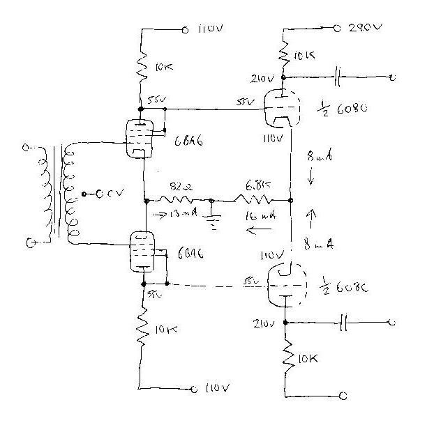
Abbey,
This is what I had in mind and maybe PRR was suggesting.


I've checked these operating points from the data, but if anyone has the time to sim them I'd be grateful.
By the way, all the lines are solid except around the 6080 halves (too faint for scanner)
best
DaveP
 
I'm totally not liking 6080 here.

Common-mode rejection is a function of both common-mode gain and normal mode gain. 6080 normal mode gain is rarely even 2, probably a ton less at this low current (so low the electrons sneak "around" the grid).

12AT7 ought to work fine. Even with the values you have. If I've thumb-computed correctly, a 55V to 100V transition on the vary-Mu plates becomes a 32V common-mode jump at 12AT7 plates.

common-mode gain = 0.7
normal mode gain ~= 40
CMRR 1/56 or 35dB

As typical final-stages run 5V-20V bias, a 32V CM jump is likely to be upsetting. Even much smaller bias-jumps are effective "tremolo" in gitar amps, so we probably don't want that.

This jump could be reduced with a larger tail impedance. A negative supply, or a transistor.

Still and all.... you propose 110V on the vary-Mu and 290V for another stage. If there is good 290V in the chassis, use it on the vary-Mu; you get 7dB or 8dB more headroom. Which of course increases the common-mode jump.

Transistor diff-amps can do a bit better, assuming 300V devices are available (selection is small and Beta inevitably lower than our 30V jellybeans.)

 
PRR,
Thanks for coming back on this.
Yes, a 6080 is far from ideal, I just used it as an example of a tube that had a grid that could swing +&- 55V, to show the principle.
Looking at the 12AT7 curves, the grid bottoms out at -8V at 300V, so how do you reckon it could cope with the swing of 55V direct coupled?

Just had a thought, wouldn't another pair of triode wired 6BA6's work in a differential amp?
best
DaveP


DaveP said:
Yes, a 6080 is far from ideal, I just used it as an example of a tube that had a grid that could swing +&- 55V, to show the principle.
The large grid swing capability has a cost; mu is quite small. You would have to put three stages in cascade to get the same gain than a more common small-signal triode.
Looking at the 12AT7 curves, the grid bottoms out at -8V at 300V, so how do you reckon it could cope with the swing of 55V direct coupled?
Look at how the cathode moves with the grid in a cath-follower configuration. Regarding CM voltage, a diff pair is just two cath-follower in parallels.
Just had a thought, wouldn't another pair of triode wired 6BA6's work in a differential amp?
Sure they would, but would they perform better than a 12AT7?
 
here's another approach from AWA. No interstage transformer but two stages of vari-mu, first stage with a slower attack, second stage with a faster attack. Note 1.6M resistors into the grid of the second stage and the LC filter on the output of the second stage.
 

Attachments

  • AWA G51501sm.jpg
    AWA G51501sm.jpg
    134.4 KB
squib said:
here's another approach from AWA. No interstage transformer but two stages of vari-mu, first stage with a slower attack, second stage with a faster attack. Note 1.6M resistors into the grid of the second stage and the LC filter on the output of the second stage.
Very interesting schemo.
The LC filter is not just any LC filter. The inductors are wound on a common core, as a result common-mode thumps are eliminated.
 
yet the DC is blocked by caps C5 and C6. Wouldn't the caps and inductor(s) combine to make a 12dB HP filter?
 
squib said:
yet the DC is blocked by caps C5 and C6. Wouldn't the caps and inductor(s) combine to make a 12dB HP filter?

I think that's the idea but as you said for common mode will be much higher atten, for the common mode L will be the lekage induction (or twice the lekage, I leave math here for someone else) and for differential mode will be the induction of both in series so about 4 times the induction of each. I don't know the specs of this transformer but this is how it'll work, worst case CMR will be 3 orders of magnitude over the signal.

JS
 
joaquins said:
squib said:
yet the DC is blocked by caps C5 and C6. Wouldn't the caps and inductor(s) combine to make a 12dB HP filter?

I think that's the idea but as you said for common mode will be much higher atten, for the common mode L will be the lekage induction (or twice the lekage, I leave math here for someone else) and for differential mode will be the induction of both in series so about 4 times the induction of each. I don't know the specs of this transformer but this is how it'll work, worst case CMR will be 3 orders of magnitude over the signal.
Any half-decent iron-core xfmr has a coupling coefficient equal or larger than 0.99; as a result the CM inductance is about 1/100th of the nominal, so CMR is probably close to 40dB.
 
abbey road d enfer said:
joaquins said:
squib said:
yet the DC is blocked by caps C5 and C6. Wouldn't the caps and inductor(s) combine to make a 12dB HP filter?

I think that's the idea but as you said for common mode will be much higher atten, for the common mode L will be the lekage induction (or twice the lekage, I leave math here for someone else) and for differential mode will be the induction of both in series so about 4 times the induction of each. I don't know the specs of this transformer but this is how it'll work, worst case CMR will be 3 orders of magnitude over the signal.
Any half-decent iron-core xfmr has a coupling coefficient equal or larger than 0.99; as a result the CM inductance is about 1/100th of the nominal, so CMR is probably close to 40dB.
Sorry, I should said 2 orders of magnitude... 3 is too much.
 
Can anyone tell me if they have a problem with the attached diagram, I apologise for my schematic drawing!

I am unsure whether it is more practical to keep the side chain balanced throughout, or unbalanced and then phase split it before rectification. The attached may be the easiest route as I plan on allowing the internal and external side chain to be mixed together - I assume the external input may need some addition gain but for the purposes of this simple diagram I have not gone into too much detail.

Something else I would like to add is a compression limiter (for lack of a better name) to the side chain, with a simple op-amp limiter. So the compression will be limited to a certain level, maybe at just a few pre selected points (-2dB, -4dB, - 6dB) I can insert this before the side chain filter unless anyone can suggest a better solution?

Just after a sanity check really, is this a worthwhile approach?

Many thanks - still learning!


Attachments

  • Bear Vari-mu SC (2).jpg
    Bear Vari-mu SC (2).jpg
    574.7 KB
Getting to the point now where I am pretty happy with the side chain concept and design but I have overlooked something quite important..

I plan to use opamps in the side chain, but obviously I will not be able to input a large signal from the output valves into opamps. I could voltage divide the signal down but then I waste all the hard work from the gain stages, so what would my alternitives be here? I could use discrete components?

I would prefer to stick with opamps because of their simplicity but if there are other options I would be happy to try them out.

Any help much appreciated

 
> not be able to input a large signal from the output valves

This is a *Limiter*, right? So there won't be any "large" from the output, just solid +4dBu (or whatever), a couple Volts.
 
Sorry I mean that if I feed the side chain from the primaries of the output transformer the signal will be conciderably larger than 4dBu.
 
Back
Top