API-ish Mic Pre Project

GroupDIY Audio Forum

Help Support GroupDIY Audio Forum:

This site may earn a commission from merchant affiliate links, including eBay, Amazon, and others.
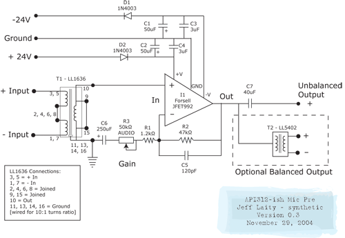
I just showed my design to an engineer at work. I explained that I have too much gain at the minimum setting. Now I have two choices:

- Use a 47k ohm trim pot for gain
- Use a 25k pot for gain, replace R2 with a 25k resistor
- Replace R1 with a stepped attenuator with values for 1k, 10k, 20k, 30k, 40k, 50k

Does the stepped attenuator gain me anything? (No pun intended.) There's the cool factor of course, but other than that is there an audio reason to use a combination of trim pot and stepped attenuator? I like having a trim pot in there so that I can reduce the level when the vocalist is about to scream out a high note, for example. But does the pot in the chain cancel out any audio advantages of using a stepped attenuator?
 
Some people argue that rotary switches with stepped resistors will sound better than a pot, but the main reasons I can see to use rotary switches are:

1) You can design any curve you like (reverse-log, log, exponential, etc.)

2) You can always recall an exact setting if you need to. This is especially handy for matched pairs, if you want them to work as closely as possible to each other.

That's about it for me.
 
Synthetic,

I think your to much gain problem is that you have aprox. +20 dB gain in the LL1636 input transformer that you have connect for 1:10 ratio. (C alternative)
You can take down the gain aprox. 6 to 8 dB if you connect the transformer for 1:5, (A alternative) or if you use the Lundahl LL1538 that have 1:5 ratio with 14 dB gain and also 1:2.5 ratio with 8 dB gain.

If you use the "classical" gain potentiometer circuit for a mike amp, there the components value is: 10 kohm reverse log. potentiometer as R3 in your schematic, and R1=10 k with the parallel C5=100 pF, R2=100 ohm and C6=470 uF, and you will get +6dB as minimum gain and +40 dB as maximum gain, and this three value relations with a reverse logaritmic potentiometer gives a ok turning behavior for the gain potentiometer.

When you use this gain structure together with a 1:10 ratio transformer you get +26 dB as minimum gain and 60 dB as maximum gain, and this 60 dB max gain is nice to have for dynamic mikes, end then it is usal to have a aprox. 20 dB pad before the transformer to handle high level from condenser mikes when you mike brass, percussion and so on.

There are some other way to connect a gain potentiometer and get near unity gain in the mike amp, for example to have the R1 as a logaritmic potentiometer instead for the R3 potentiometer, but this alternative can be more instable under 6 dB gain.
Some maunfacturer have solve the "wide gain range" problem with a two step mike amp circuits with two op-amps and dual gain pots, and some have place one of the potentiometer half after the mike transformer secondary before the first op-amp input and the other half in a common feedback connection.

--Bo
 
Yikes! I missed that ground on the cap. I was looking at a line amp schematic which had no ground shown on the cap. Sorry about that!
There is no dc ground ref, but the the ac goes thru the cap.

I changed R2 from 130k to 56k as per D.K's suggestion and the noise came down a bit and the pre sounds better. You will notice some tone changes as you adjust the gain pot, so there is a definite sweet spot that can be tweaked depending on mic choice. The Melcor I am using makes my beta 57 sound like a high end mic. There are a couple of 1000 pf caps on the input legs of the transformer that goes to ground. There might be some tone shaping going on there, so you might give it a try.Thanks to PRR for the bailout, again!
cj
Oh, and how does that thing sound, anyway?
 
I think I'll try a 50k audio taper for a gain pot. I think that stresses the op amp less than 10k trim and 10k feedback resistor, right?

We thought about rewiring the transformer as 5:1 instead of 10:1, but that only gets us 6dB. By making the trim resistor a 50k, I keep the high end of the gain scale and lower the low end, which is what I want to do. I'm assuming that the gain range will be approximately 20dB to 52dB. Plus, I think the API input transformer was about 8:1 (at least the copies I've looked at were) and I'd like to come close to that sound, only with hot-rod components.

I can't really tell how it sounds yet because it distorts the heck out of my FW-1884. :grin: My new tube mic should be here by the time I have it up and running, I'll post a few audio clips once that's happening.

Thanks once again to everyone who has helped me out. :thumb: :guinness: :guinness:
 
Crap, the only 50k pots I can find don't have 6mm shafts like the expensive knobs I just bought. :cry: Maybe I can find a way to shoehorn them onto .25" shafts.
 
The latest schematic, for anyone keeping score:

Forsell_API_preamp_03.gif


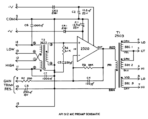
A nicer scan of the API 312 schematic for comparison:

api312.gif
 
[quote author="tharnicasync"]What is the purpose of C5 in this circuit. [/quote]

:roll:

which C5 ?
Jeff's or API's circuit ?

Jeff's C5 - 120pf - opamp compensation
API's C5 - 220pf - input trafo loading ... (stops ringing)
 
The R2=47k is too high vakue in synthetic's schematic. That resistor should be lower because of noise considerations.
10K should be an optimal value and R1 should be around 10 to 100 ohm depending on the gain you need. The gain pot should be 10K.
The Lundahl1636 do not need the zobel network like in the original schematic because the resonance is somewhere around 100KHz.
C5=120pF is good for the 2520 opamp but too high for the 992. You will need a much smaller value.

chrissugar
 
[quote author="Kev"][quote author="tharnicasync"]What is the purpose of C5 in this circuit. [/quote]


which C5 ?
Jeff's or API's circuit ?
[/quote]

Thanks, Kev. I meant Jeff's circuit...

kelly
 
[quote author="chrissugar"]The R2=47k is too high vakue in synthetic's schematic. That resistor should be lower because of noise considerations.
10K should be an optimal value and R1 should be around 10 to 100 ohm depending on the gain you need. The gain pot should be 10K.[/quote]

This would give me a gain of 1-10, right? I tried this application and I got feedback at the lowest setting, but my trim pot might have been wired wrong. Forsell lists a 2k resistor for R1 and R2, so I can see where 50k might be too high.

The Lundahl1636 do not need the zobel network like in the original schematic because the resonance is somewhere around 100KHz.

Zobel network being the 1000pf cap to ground? Just curious.

C5=120pF is good for the 2520 opamp but too high for the 992. You will need a much smaller value. chrissugar

Looking at the application notes on the Forsell site, he lists a 10pf cap in the feedback loop. So you're right, 120pf is too high. Thanks for that catch. The PDF application notefro this part is here, if anyone is interested:

http://www.forsselltech.com/JFET990-2a.PDF

Perhaps I should email Fred for his opinion of the circuit. Once again, thanks for all of your help. :guinness:
 
Am I correct that if R1 is 100 ohms, R2 (feedback) is 10k and the trim is 10k that I get a gain of .99 to 100, or 0 - 40dB? I'll give that a shot this weekend, but I'm a little nervous using a linear pot for that much gain. Oh well, I'll just order an exponential 10k if it works out. More parts, yay. :grin:
 
Fred must still be in Australia. I found a similar schematic on his site where he specifies a 10k feedback resistor and a 10k rev log gain trim:

http://www.forsselltech.com/schematics/JE16%20Mike%20Preamp.PDF

I guess I'll go back to a 10k feedback resistor and see if I can get that to work. If I did want to put a log pot in my circuit, would it have to be a reverse log?
 
Hey synthetic

You are right, if the feedback rezistor is R2=10K and R1=10 ohm the gain from the discrete opamp is 1000 that equals 40dB. The Lundahl1636 in 1:10 configuration will give you 20dB gain. The maximum gain from this preamp would be 40+ 20=60dB.
The zobel network is a resistor in series with a capacitor that is conected paralel with the transformer secondary, in this case look at the original API schematic, R4=5K1 series with C5=220pF.

The schematic you mention [http://www.forsselltech.com/schematics/JE16%20Mike%20Preamp.PDF] is a very good guide for a modern API type preamp. As I said before the C6 in your schem should be a larger value, and also of high quality [look at the Forssell document, 4700micro/6.3V]

chrissugar
 
CJ wrote:
"I had a 130k for R2 and it was not that bad. 56k sounds very nice. 10k might dump too much current into Q2."

What current CJ ? I supose you talk about the transistor from the inverting input. The Forssell opamp is a FET discrete opamp, no input current.

chrissugar
 

Latest posts

Back
Top