midwayfair
Well-known member
Working on one of these:
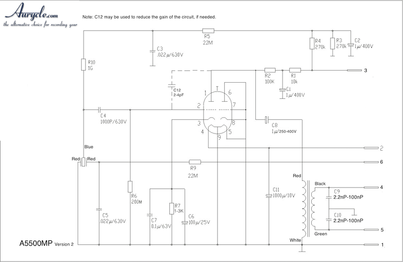
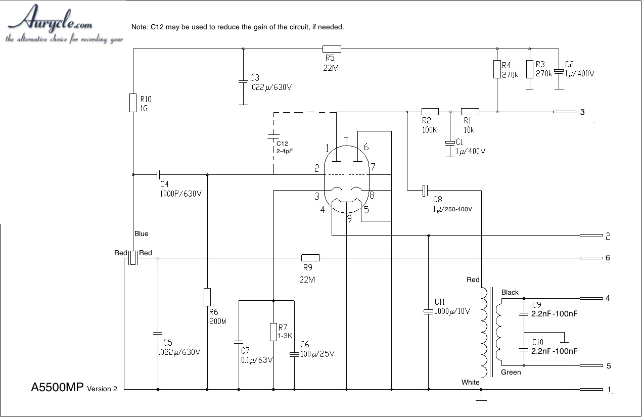
http://www.aurycle.com/manual/a5500mp-schematic_v2.jpg

First thing is I'm interested in removing the input cap.
EDIT: Removing the input cap can't be done here without significant modifications, scrap this idea.
They don't have a schematic for the power supply, but I believe pin 6 is the half (or variable) voltage point for the polar patterns, right? (Because pin3 has to be the high voltage for the tube anode.)
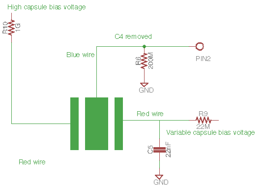
If I'm analogizing this to the FET mics I've built, I would move the R10 connection to the rear capsule instead of the backplate and disconnect the rear capsule connection from ground. But I was wondering if it might be easier to instead connect the red wire currently going to the rear capsule directly to a pin2 connection (like the hole left by leaving off C4).
My other question was C8 and C6. C6 looks like overkill, but then again, I haven't build microphone stuff with tubes, only guitar amps. I read somewhere (don't remember where -- maybe on the Fox audio page?) that the mic can be a little rumbly. I'm most likely replacing the transformer with a lower ratio (a 1:8 cinemag that I have lying around) and was initially going to bump up C8, but now I'm wondering if I ought to decrease it to .47uF instead or just leave it alone.
My last change is to use a 12AY7 instead, to bring the output impedance back down. (The 12AX7 would have been a 600R output impedance with the 8:1. I think the 12AY7 is probably the right call even with the 9.5:1 that came with the kit.) Is there anything else I need to change to accommodate this? I know the ELA251 build I have has a 1.8K on the cathode, and that's a 12AY7.
http://www.aurycle.com/manual/a5500mp-schematic_v2.jpg

First thing is I'm interested in removing the input cap.
EDIT: Removing the input cap can't be done here without significant modifications, scrap this idea.
They don't have a schematic for the power supply, but I believe pin 6 is the half (or variable) voltage point for the polar patterns, right? (Because pin3 has to be the high voltage for the tube anode.)
My other question was C8 and C6. C6 looks like overkill, but then again, I haven't build microphone stuff with tubes, only guitar amps. I read somewhere (don't remember where -- maybe on the Fox audio page?) that the mic can be a little rumbly. I'm most likely replacing the transformer with a lower ratio (a 1:8 cinemag that I have lying around) and was initially going to bump up C8, but now I'm wondering if I ought to decrease it to .47uF instead or just leave it alone.
My last change is to use a 12AY7 instead, to bring the output impedance back down. (The 12AX7 would have been a 600R output impedance with the 8:1. I think the 12AY7 is probably the right call even with the 9.5:1 that came with the kit.) Is there anything else I need to change to accommodate this? I know the ELA251 build I have has a 1.8K on the cathode, and that's a 12AY7.


