Aux sends and returns in a mixer project- what's your opinion?

GroupDIY Audio Forum

Help Support GroupDIY Audio Forum:

This site may earn a commission from merchant affiliate links, including eBay, Amazon, and others.
boji said:
Perhaps getting deep attenuation here is not so important, given overall volume can be adjusted at the return pot... I mean, why hit an fx unit weakly only to get more noise out of the bargain?
Your proposed schemo does not do what you want; it gives more gain, when you want attenuation. Unfortunately, attenuation with a single inverter requires a FB resistor that's significantly lower than the bus injection resistors. For 15dB attenuation, you need about 10k. That is at the cost of slightly increasing the noise gain.
If I were you, I would keep the DOA to drive the xfmr and instal a VLN opamp as summing amp, and the pot in-between.
 

Attachments

  • VE mixer trim.jpg
    VE mixer trim.jpg
    73.8 KB · Views: 12
Thank you for your little sketch!  :eek:  :D
BTW, I forgot the aux bus resistors are 39k not 47k. 

So, it is confusing to hear you say it won't work, since it's from the API skiz. This has to mean I'm missing something. It makes me think the return module needs to be seen in context with the send module section! Perhaps within that ghost skiz is a summer + volume pot that justifies the return module's A1 gain, which acts very much like what you're suggesting in your previous post.
9KeMHMe.jpg


I wouldn't ask you to go pouring through difficult-to-read photocopies of the 548 skiz, but I'm curious what comes before the "From Echo Send Sum Bus" (Apologies for the large pictures)
NMD79RC.jpg
 
boji said:
Edit2: Ian, again regarding the Aux Group 'On' switch, are you thinking it is redundant given the mute later on?

TBH I did not realise there was a mute later on. My only point was that an aux send on/off button is unusual. Doesn't mean you should not have one if you think it is necessary.

Cheers

Ian
 
boji said:
So, it is confusing to hear you say it won't work, since it's from the API skiz.
I didn't say it wouldn't work. I just mentioned there's a (small) price to pay in terms of noise.
The API design is somewhat a little flawed. The correct way is to separate the summing amp from the output stage, so they can be optimized separately. Because of the high cost of DOA's they had to compromize somewhat.
Separating the summing amp and the output stage gives you the opportunity to use a VLN summing amp (which the 2520 is not, but the 990 is) and use a DOA for its drive capability (which is not of a terrific value when driving a 10+k input).
Now if you're good with a range of adjustment of about 15-20 dB and accept a little degradation in noise, the API schemo is fine.
 
Bosi , you know your channels can act as returns. 

The Aux send summers could be a simple single trim/gain knob and mounted behind a panel with a solo afl in a a single strip with 6 trims on it.  You don’t need to duplicate the E528 with combo send return.   

Also look at the 2488 brochure and patch bay layout.  It always helps me see things besides just looking at the Schematics.  I also like looking at the modules and comparing the Patchbay I/0’s to tie back into the schematics.

The only time I’ve had noise issues in my 2488 is when there has been a problem in the circuit of the Aux’s.  That does not mean using new topology is not a good way to go,  it just means that later consoles with 48 channels have more elaborate circuitry to handle noise issues. 
 
You know your channels can act as returns. 
Hmm.  I'd get the ready-made hpf, polarity, and 500 inserts out of the bargain. For aux send groups, go with the standard aca --> fader--->boost and leave the balanced sends with afl sent to patch for channel insertion, normalled to monitor in's. Sends VU
could be a mult from the 2503's. Returns VU would come from the channel. Damn, I could even switch the sends VU over to the group channels after gains were set...  I'd have to be careful about send feedback loops but this would replace the space needed for specialized return cards, bumping the channels from 18 back up to 24.

Thanks fazer, this is something to seriously think about... Include itb routing flexibility,  and it starts to feel like simplified, forward thinking, at the cost of a little patch panel dancing.
 
I agree with fazer. Back in post 4 I said "In the limit, returns can be fed to the line input of a channel so all the facilities a channel has will be available to and FX return."

Cheers

Ian
 
I didn't say it wouldn't work. I just mentioned there's a (small) price to pay in terms of noise.
I appreciate your recommendations and reasoning Abby. I may come back to your 990 solution, as I think I've even heard Jeff mention he uses them in some of his aca's. In the meantime, I will draft up a simplified aux group module, and down the road try to implement the sends patch idea and see what it does for workflow. Still have the group modules to concoct too!

I'll post back after draft. Thanks again everyone!
 
Attached is probably the simplest AUX send master and aux return.

Cheers

Ian
 

Attachments

  • Screenshot at 2018-11-18 17-21-29.png
    Screenshot at 2018-11-18 17-21-29.png
    211.8 KB · Views: 33
Hello friends.

Ian mentioned the rather obvious choice to omit the 1st tx in the CAPI aca/bo since it's not sending any balanced signal anywhere. Would you mind talking a look at this and tell me if anything looks wonky to you? Thank you!

zw4d9cm.jpg
 
i'm not really sure but I believe that API uses a simple pot wired as a voltage divider after the ACA's transformer and that's it.

Paolo
 
pahstah said:
i'm not really sure but I believe that API uses a simple pot wired as a voltage divider after the ACA's transformer and that's it.

Paolo

Neve did something similar on occasion. A 2K2 LIN pot across hot and cold with a 1K pull up resistor to give about -10dB at the half way point and a maximum load of about 600 ohms. It does require and ouput capable of driving a 600 ohm load though.

Cheers

Ian
 
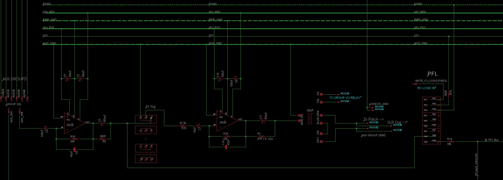
Since you're not driving any xfmrs, you don't need R1 & R9.
Yessr, thanks Abby.  R9 is not making much sense, but R1 I thought is part of A2 which is driving a 2503. Are you saying even so, R1 is not needed?
R1 / R9 in parallel with "DC blockers"C3 / C11 ?
DC path to fader...
Thanks Newmarket. I'm supposed to remember dc makes for scratchy pots.... R9 was a vestige of A1's 2623; Removed.
As yet, i'm still not sure about R1. I am ASSuming it is there to properly load A2 but perhaps without the voltage divider on A1's now omitted tx, R1 is no longer needed (question I'm humbly putting to you guys)  :D

i'm not really sure but I believe that API uses a simple pot wired as a voltage divider after the ACA's transformer and that's it.
Thanks pahstah, yes, that's how Jeff's ACA/Bo has it-- straight from the old 70's API playbook.
Again, I inferred from a question Ian posed elsewhere about the need for TX1 to mean if it's not supplying balanced signal anywhere, why include it?  Sound / isolation-wise it couldn't hurt, but omitting it would make it possible to fit three aux sends on a pcb where otherwise only two would fit when using two tx's and two 2520's per send.

Unless anyone thinks removing A1's 2623 hurts the performance or 'vibe' of the combiner & send, I'll take the extra space over the extra iron, since these are not main channel aca's.
 
One question to ask, do you really need / want transformers and discrete opamps for auxes? I would be more inclined to make them as clean and neutral as possible.
 
One question to ask, do you really need / want transformers and discrete opamps for auxes? I would be more inclined to make them as clean and neutral as possible.

A fair question.  I honestly don't have comparative experiences to know what I'd be losing by keeping it old school.
Anyone else with a decent older console care to comment?
 
Back
Top