Banzai's KM84 DIY Body & PCB kit build thread

GroupDIY Audio Forum

Help Support GroupDIY Audio Forum:

This site may earn a commission from merchant affiliate links, including eBay, Amazon, and others.
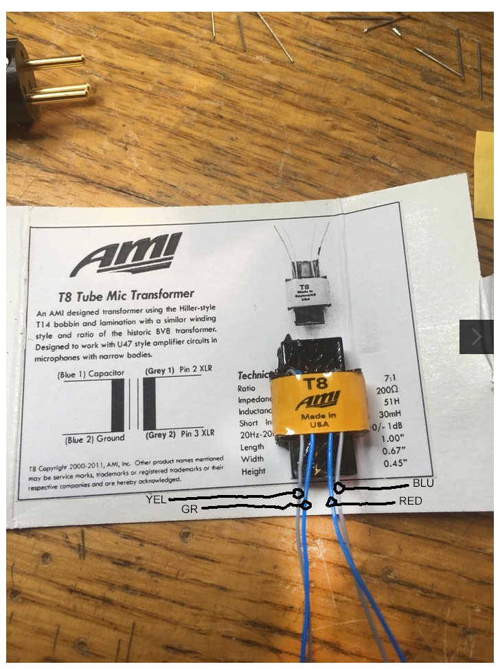
I also built a mic with the AMI.  Mine was less symmetrical than the one in the picture... on mine, there is a blue+grey pair that is anchored near the middle of the transformer and a pair that is more near the edge.  I think I measured with an ohmmeter to determine which is primary and which is secondary; I used the center blue+gray pair as the high: I used a Sharpie felt tip marker to put a stripe on those two.  That mic came out Pin 2 = high: correct in my world. 

FWIW, I took my mic to one of the designers /developers of Audio Precision test gear to help me with biasing and he scratched his head for several minutes about the 'mystery' wire coding--it really bugged him. 
 
AMI%20T8.jpg


Be sure to leave enough extra grey wire to reverse the leads if the mic's polarity is reversed.

I finished my mic by cleaning the brass well and spraying it with a couple of coats of lacquer.  I think that's the easiest way.
 
I would double check the wiring with the guys at AMI/Tab. I've built other mics using their T13/T14 transformers and one color set of wires is primary and the other is secondary. The one issue that I with a T13 is that the label for secondary and primary were printed opposite of what they actually were, but they were the same color for each side of the transformer. I don't know the DCR reading for the T8 but for the T14 is about 900R for the primary and about 20R for the secondary. The trick to determining polarity (at least what I've found) is you pick a side where the pairs of leads come out of the transformer. So in the case of the T8, I would use the left blue/gray pair as the (+) polarity for primary/secondary, so blue(capacitor) and gray (Pin 2) and the pair on the right as the (-) pair (Ground and Pin 3). The label on the box could be in error as I have had, but the color leads were still grouped together just backwards.

I have a pair of T8's waiting to be put in my kits when they arrive. I'll take some measurements later and get back to you.

Thanks!

Paul
 
Yes, the blue wires are the primary and the grey wires are the secondary. The left pair of blue and grey come out of what looks to me like the top of the coil and the other pair the bottom. Which pair is top and which is bottom really doesn't matter as long as the primary and secondary aren't mixed up. If you connect the secondary wires incorrectly and the polarity is wrong you can always reverse the leads as long as you don't cut too much off. I would suggest checking the polarity against other mics under any circumstances. Having one mic wired with reverse polarity and not knowing it could be a very unwelcome surprise.
 
Correct. I got a bit confused to your post as you mentioned using a blue/gray pair as the primary and I think you meant to say positive. I think. And a reverse polarity mic wiring is indeed and unpleasant surprise.

At any rate, for those who want to verify your leads (in case you do get one that is backwards), I took measurements off of my T8 and for the primaries (blue) I get 220 ohms DCR and the secondaries (gray) I get 20 ohms.

I am curious how these will stack up against the Cinemag versions I've already built.

Thanks!

Paul
 
Yeah sorry guys--I m uh idiot--I edited my post above like 5 times.  I have transformers/transformer diagrams on the brain and I just now edited my post for a sixth time because it was wrong. 

BOTTOM LINE: the STRONG impression I got from the tech I worked with on biasing--a man who is looked up to by my usual guy who was the chief engineer at Jensen Transformer when Deane Jensen was alive--is that for there not to be proper full documentation of what is happening with each transformer wire--is just not professional and a recipe for trouble. 

As to the sound quality of these mics, the passage of time will tell the full story but, so far I am pleased when compared to the 2 hand picked Neumann KM84's I already own. 
 
I got my round 2 parts yesterday.  I didnt see the insulated turrets in the BOM, and didn’t get any with body parts. Can anyone tell me what size these are, so I can order the correct ones the first time around? I’ll probably look at mouser since I’m in the states. Thanks.
 
4th item on the list:

https://www.mouser.com/ProjectManager/ProjectDetail.aspx?AccessID=f5036488e2
 
maarvold said:
4th item on the list:

https://www.mouser.com/ProjectManager/ProjectDetail.aspx?AccessID=f5036488e2
Thanks, I found them, they we’re stuck hiding  in  the mouser bubble wrap!
 
To make the BOM list easier to navigate you can sort by 'Customer No'.

Puts everything in order.


Attachments

  • Screen shot 2019-02-25 at 11.06.14 AM.png
    Screen shot 2019-02-25 at 11.06.14 AM.png
    8.6 KB
I'm a bit confused about the bias processing.
Ruud described it in two ways.
On the other hand its described to feed the signal through the gate (middle leg) with a capacitor.
At my opinion, I must connect my oscilloscope to the drain leg to bias the FET.
The other explanation is, to connect the capacitor to the capsule, which would be the  source leg and feed the signal in it.

I'm confused and was not able to bias the mic.
The explanation from Ruud is flawless, but I think I've a thinking error.
Hope somebody can help me.
 
maarvold said:
... is that for there not to be proper full documentation of what is happening with each transformer wire--is just not professional and a recipe for trouble.
It is completely pointless. Doesn't add any cost to use different colours, and save everyone the hassle. Same issue on all their wired transformers.

I'll talk to Moby and see if he can do a run of BV107's for us :)
 
Got my mic up and running.  Sounds lovely!

Graeme, thanks for the build guide.    The only things that I would add to it would be to make sure to orient the tantalum capacitors correctly, and when you attach the cone to the front, mic sure the wire is oriented the way you want it to be (toward the correct turret and above all the other connections).

Craig
 
TillM said:
I'm a bit confused about the bias processing.
Ruud described it in two ways.
On the other hand its described to feed the signal through the gate (middle leg) with a capacitor.
At my opinion, I must connect my oscilloscope to the drain leg to bias the FET.
The other explanation is, to connect the capacitor to the capsule, which would be the  source leg and feed the signal in it.

I'm confused and was not able to bias the mic.
The explanation from Ruud is flawless, but I think I've a thinking error.
Hope somebody can help me.

I clipped my signal generator to the mic. Positive to the spring loaded contact touching capsule(without capsule). Negative to ground/chassis/pin 1 of the mic. I connected an XLR "y"(f/m/m) to the mic. I connected one side of the "y" to a pre-amp providing +48V. I then connected my oscilloscope(positive to pin 2 and ground/chassis to pin 1) to the other side of the "y". I understand that there is DC voltage at this point, but it did not SEEM to affect my biasing process. I can say that I fried two 2N3819s by sending way too much voltage at them. Shouldn't need more than 1V @ 1Khz, maximum, to determine bias at max input. Not sure when they "give way" but 10V  is definitely enough. Was for me, twice. Check for continuity/resistance at your primary and secondary of your output trafo before starting. I received some faulty ones(2 at once) from a particular company during this endeavor. That combined with my fried transistors made for some real GDIY troubleshooting.
 
Here's a link to some stuff about biasing that might be helpful:

https://www.dropbox.com/s/rx6q7vprdjfy9hi/DIY%20KM84_Biasing%20Procedure.zip?dl=0
 
Can the 10k, 10M, and 2k2 be 1/4W instead of 1/2W? I don't want to start a sea of  questions asking can this part be substituted for this one, but I feel that the several I built when the first round happened I used 1/4W for those values and I was fine. I'm mostly just trying to use parts that I have in hopes of lessening the inventory of components that I already have.

Thanks!

Paul
 
I need some help with my two DIY KM84 mics:

This is my first build of FET-mics, so I might have missed something.

I have two problems:
Both microphones have a self-resonance (see the spikes in the picture).

One mic has a normal output level (compared to my KM184), the other mic has about 6 dB lower output. They both sound OK (sounds very flat, all the way down. More so than my KM184. The high-end is not as “essy” as the KM184, also as expected).

I have not adjusted the bias yet. I started with R3 at 10k and the self-resonance was very bad. Dropped it to 3.9K, and the self-resonance was better but still there. Same thing for both mics.

And yes, the PCBs are very clean.

Does the self-resonance have to do with the bias adjustment or is it something else?
I’m using the 3U GZT-84 transformers that came with the kit, but I don’t that has anything to do with my problem.
 

Attachments

  • DIY KM84.jpg
    DIY KM84.jpg
    152.5 KB
I finally got around to biasing my four kits from the first round with Cinemag transformers and was having a bit of trouble getting a reading with the 1000pF cap inline with the signal generator and the brass contact for the capsule. I thought it was my preamp or my generator, but I tested those straight to the scope and they were fine. I wound up ditching the cap and when straight from the generator to the mic and I was able to get a stable sine wave on the display.

I tested these with my voice and they sound really big and smooth. And stunningly quiet. I just need to order some parts for the other two kits with T8's to see how they compare. Also, they need a couple of seconds to charge the capsule. I had one make intermittent clicking sounds for several seconds when I first applied phantom power, but then it stopped and I have not been able to reproduce that noise sense.

I've attached a photo of what I was getting with the cap inline. It was a film capacitor and I don't know if I was supposed to use a ceramic one. The generator is an NTI Minirator Pro and didn't seem to be affected by the polarization voltage.

Also, for these kits I used 1/4 resistors all the way through as that is what I believe was on the original BOM and I haven't noticed any problems so far.

Thanks!

Paul
 

Attachments

  • Osc1.jpg
    Osc1.jpg
    392.5 KB
Back
Top