Banzai's KM84 DIY Body & PCB kit build thread

GroupDIY Audio Forum

Help Support GroupDIY Audio Forum:

This site may earn a commission from merchant affiliate links, including eBay, Amazon, and others.
Potato Cakes said:
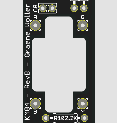
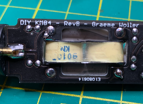
For the leads you follow the drawing you posted from Cinemag's website. The transformer will just fit in there and might require some very minor trimming/filing to get it to fit. It does just float in there but won't move when the PCB is inserted into the body. You can also do what I did and apply a small amount of hot glue for added security.

Thanks!

Paul
I asked Cinemag for a quote, they told me they can send the trafo with the leads hooked up internally, meaning you have four leads, or the 8 leads out. What did you guys choose?
 
I would think having access to all eight leads would be ideal so everyone can stick to the original schematic and the layout provided. That way the questions and confusion on hooking it up would be kept to a minimum. I am only speaking for myself, of course.

I got my threads crossed. Four wires would be easier with this board yes. The AMI option only has four wires.

Thanks!

Paul
 
The boards in this thread only have pads for 4 connections...The CM-5722W is the one with 4 leads.  I would think it would be simpler to use since there is no impedance switch on the output side of the transformer,  unlike the original, so there is really no need  for the extra wires.  Use the data sheet they wil send as the colors of the wires for primary and secondary are different from those on the PCB printing, at least on mine. 

If you use the other more traditional one, just be careful how you hook up the unused leads so that you get the windings in the proper sequence. 

David at  Cinemag says they are identical otherwise

—Mark
 
Cinemag 5722 (8 wires):
R - Red
G - Green
B - Blue
Y - Yellow

Cinemag 5722W (4 wires):
R - Red
G - Brown
B - Orange
Y - Yellow

KM84-PCB-Transformer-pads.png
 
Banzai...that’s awesome.

And Paul, I didn’t want you to think I was being critical...I just thought it was easier not to have the extra leads for this application.

—Mark
 
Has anyone been having RF/induction issues manifesting as noise in these microphones? I was using these in an orchestral situation and had to mute them because of noise. Took them home to troubleshoot and my phone induced the same noise from 3 feet away. Noticeable hum from large transformers a few feet away also. Phone turned off, issue gone. Not really usuable in a group of 60 with cell phones in their pockets. Did I do something wrong or miss something during assembly? They have been great, otherwise. Ideas?

-Brian
 
iturnknobs said:
Has anyone been having RF/induction issues manifesting as noise in these microphones? I was using these in an orchestral situation and had to mute them because of noise. Took them home to troubleshoot and my phone induced the same noise from 3 feet away. Noticeable hum from large transformers a few feet away also. Phone turned off, issue gone. Not really usuable in a group of 60 with cell phones in their pockets. Did I do something wrong or miss something during assembly? They have been great, otherwise. Ideas?

-Brian


Hello Brian,


I know the original KM84s from the late 80‘s,they were prone to pick up noise from everywhere on stage,e.g. lights and dimmers.Although I like their sound very much they sometimes were not useable.Issues went away by swapping to Schoeps,but that‘s a different story.
I don‘t know if the clones behave the same but have ordered them and will find out anyway.
If they do then I‘m sorry to say that either you gain control over the musicians and don‘t allow them to have cellphones with them while recording (I‘m in the position to do so) or the hard way and change microphones to different types/brands.


Hope to have helped,


best regards,


Udo.
 
Hello,

for those who are using the 3U GZT-84-Transformer,the Primary DCR should be around 920 Ohms,the Secondary around 42 Ohms.
Just to let you know.

Best regards,

Udo.
 
kante1603 said:
Hello,

for those who are using the 3U GZT-84-Transformer,the Primary DCR should be around 920 Ohms,the Secondary around 42 Ohms.
Just to let you know.

Best regards,

Udo.
Good tip. I'll add that the lead coloring is the same as the Cinemag 4 wire posted above here^
 
Hi Brian!

I've built two KM84. They both pick up RF-noise, from cell phones and cell phone towers.
One just a little bit, but the other one is practically useless.
I have not been able to determine why they are different.

Have anyone found a solution to this problem or maybe know why they are so sensitive to RF-noise?

- Stefan
 
Any tips on how to get the three tiny screws out at the bottom of the body? On one of my bodies, they came out fine. On the other, they are way farther down, and super tight. I’ve heard they strip easily, so I’m trying to avoid that.

Thanks,

C
 
Colorblind said:
Any tips on how to get the three tiny screws out at the bottom of the body? On one of my bodies, they came out fine. On the other, they are way farther down, and super tight. I’ve heard they strip easily, so I’m trying to avoid that.

Thanks,

C

If screws are all the way in you can pull the body tube off. Much easier to unscrew from just the connector housing.

Recommend replacing them with stainless steel M2 x 3mm. You can also just use a single regular M2 screw. Holds just fine.
 
To those with the Haufe transformers - how are you mounting them on the Rev B boards? Are modifications to the PCB required? I'm gently playing Tetris here trying to find a fit, but worried about the delicate leads on the trans. Any pics of your installs or guidance would be much appreciated. Thanks!
 
Hi BramK,
I remember, that I put a file and made it bigger.
Then you can push it in, like the cinemag ones (as seen on the pictures).
But I've to say, the difference between the Cinemag and Haufe transformers is not noticeable.
 
The 3U and Cinemag were both slightly too large for the cutout for me.

I have a set of files for guitar work and used a small one to slightly enlarge the cutout. You could use a dremel or whatever you’ve got (making sure not to cut into the surrounding traces)

I was thrown off at first but I like that the hole was slightly too small. It took very minimal filing to make the transformer fit and then I was able to get a really nice fit that doesn’t require glue or anything.
 
Thanks Till & Fuzz,

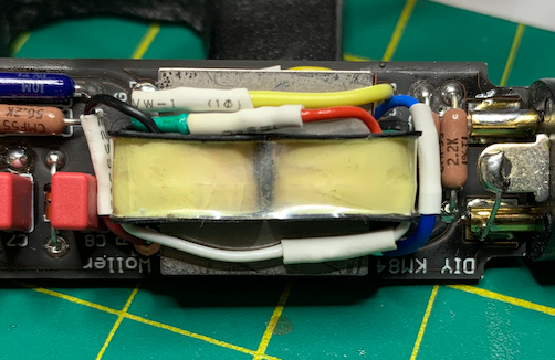
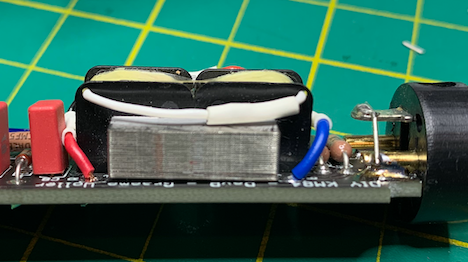
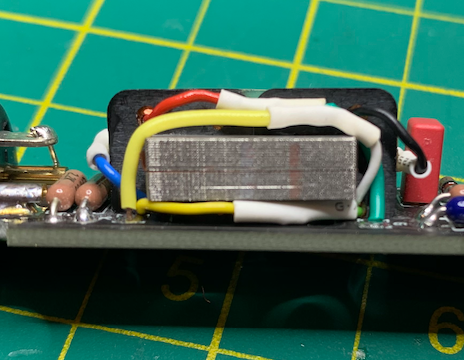
I ended up using a file on a few edges and was able to fit the Haufe in snuggly.  Here are some photos of orientation for anyone else using the Haufe:

sR0VxB6.png

1IGQkXY.png

OHDG0dR.png

vLaEjFz.png


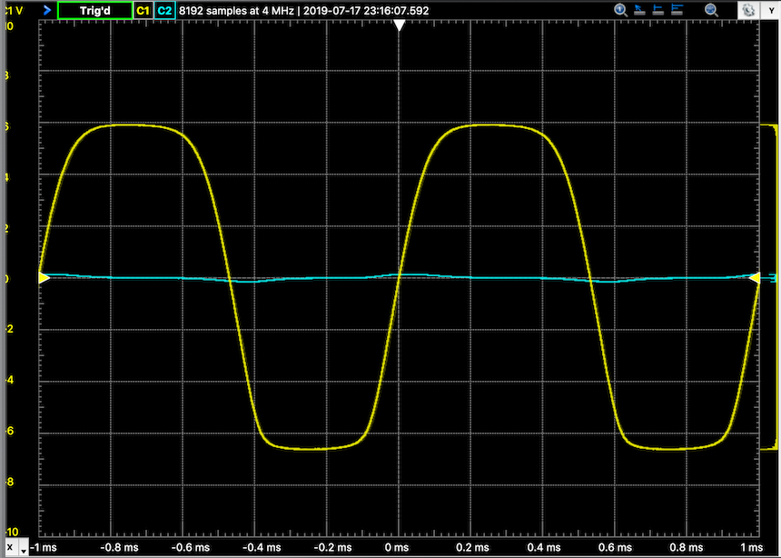
In regards to bias'ing, I ended up with 6.73K on mic 1 and 7.96K  on the other. Does this look symmetrical enough? The negative wave is narrower than the positive swing. Signal generator was applied directly to the capsule pin without a 1000pf cap (I tried using one but the scope reading was crazy and phasing with it in series), scope probe attached to the drain and grounded on xlr pin 1.

3aMPv36.png


Mic bodies are off at the powder shop!
 
Hi Bram,
yes this should be more than okay !
This is how my Haufe ended up in the pcb.
Cool that it worked with the scope.
After I damaged two fets with using a scope (my fault), I put my DMM on the capacitor backwards and turn the trimpot after I read 10v with my probe.
 

Latest posts

Back
Top