Banzai's KM84 DIY Body & PCB kit build thread

GroupDIY Audio Forum

Help Support GroupDIY Audio Forum:

This site may earn a commission from merchant affiliate links, including eBay, Amazon, and others.
Bram, 
I've got 4 mics sitting with just the transformer wiring to  connect.  After pulling one wire out of a transfo, I gave up.
Could  you post the definitive wiring for the Haufe transformers.
 
Hello,


did my 3 kits finally, biasing went well.
Thank you both Mike and Graeme for these wonderfull kits,it was a pleasure building them.
I can confirm that the supplied set screws should be exchanged to better ones.
For the transformer I had the 3U types,with a bit of „dremeling“ they went in well in the end.
Two drops of hot glue hold them in place nicely.
I did a quick testing today,and I was very happy with what I heard.A silky top end,just like the originals,never harsh.
Attached pic of proof during test setup.


Best regards,


Udo.

(Edited typo).
 

Attachments

  • 0D53FD00-25D7-463C-B022-56BCC8B2F971.jpeg
    0D53FD00-25D7-463C-B022-56BCC8B2F971.jpeg
    1.8 MB
Winetree said:
Bram, 
I've got 4 mics sitting with just the transformer wiring to  connect.  After pulling one wire out of a transfo, I gave up.
Could  you post the definitive wiring for the Haufe transformers.

Hi Winetree, apologies for not responding sooner, I wasn't getting thread updates.

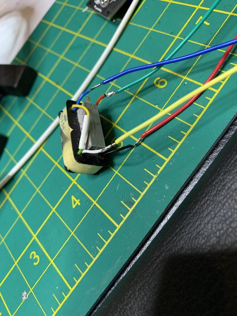
1. On the Haufe transformers, on the side that has only 2 white wires,  solder these together.
2. On the opposite side, solder together the yellow and green wires.
3. Then follow the color conversion guide below to connect to the PCB:

HAUFE --> CINEMAG (PCB Designation)

Black  ---->  Red (R)
Red      ----->    Green (G)
Blue  ------>  Blue (B)
White ---->  Yellow (Y)

To make things less confusing, I extended the Haufe leads with the cinemag color wiring.

xv2UapFl.jpg


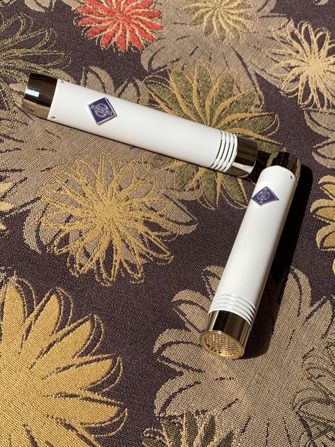
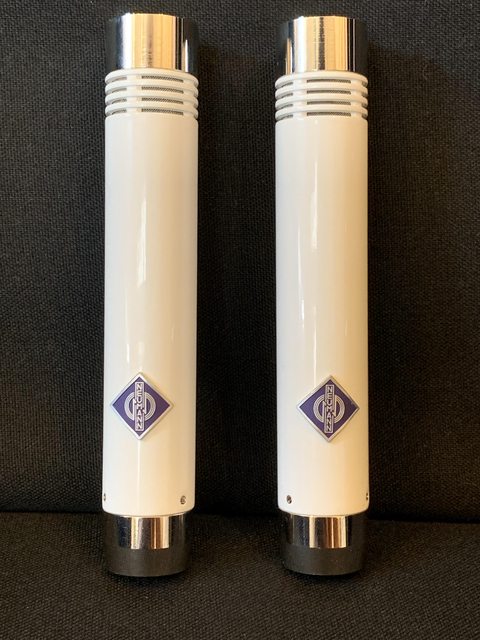
And here are the finished mics after painting (and Neumann badges... just for funsies  ;D)

BHe15YWl.jpg

loqS4Jrl.jpg


Thank you Banzai and Graeme, I've only had a few moments to test these out on acoustic and voice, but I'm loving what I'm hearing so far - they sound clear and smooth and the noise floor is impressively low. Not experiencing any RFI/EMF interference that a few others had mentioned.

 
Congrats to your builds.


May I ask how you removed the mesh out of the brass tubes for painting?
It looks like they are glued in?


Thank you in advance,


best regards,


Udo.
 
kante1603 said:
Congrats to your builds.


May I ask how you removed the mesh out of the brass tubes for painting?
It looks like they are glued in?


Thank you in advance,


best regards,


Udo.

I soaked them in acetone for a few minutes.
 
Winetree said:
On the first group buy, the screen was a separate, cut rectangle you placed in the mic.
Did they glue them in on the second batch?
Hello Winetree,


yes,looks like glue put on 4 spots inside.


Best regards,


Udo.
 
BramK said:
Hi Winetree, apologies for not responding sooner, I wasn't getting thread updates.

1. On the Haufe transformers, on the side that has only 2 white wires,  solder these together.
2. On the opposite side, solder together the yellow and green wires.
3. Then follow the color conversion guide below to connect to the PCB:

HAUFE --> CINEMAG (PCB Designation)

Black  ---->  Red (R)
Red      ----->    Green (G)
Blue  ------>  Blue (B)
White ---->  Yellow (Y)

To make things less confusing, I extended the Haufe leads with the cinemag color wiring.

xv2UapFl.jpg


And here are the finished mics after painting (and Neumann badges... just for funsies  ;D)

BHe15YWl.jpg

loqS4Jrl.jpg


Thank you Banzai and Graeme, I've only had a few moments to test these out on acoustic and voice, but I'm loving what I'm hearing so far - they sound clear and smooth and the noise floor is impressively low. Not experiencing any RFI/EMF interference that a few others had mentioned.

Those look amazing! I gotta powdercoat mine now  ;D
 
jrmintz said:
AMI%20T8.jpg


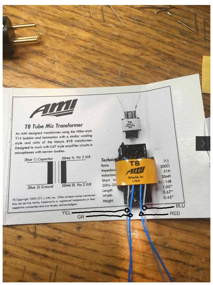
Be sure to leave enough extra grey wire to reverse the leads if the mic's polarity is reversed.

I finished my mic by cleaning the brass well and spraying it with a couple of coats of lacquer.  I think that's the easiest way.

I just finished one of mine using the AMI transformer. My wiring looks similar to this, but left to right goes: blue, grey, blue, grey.  The transformers came in bubble wrap with no data sheet. My DMM showed a higher resistance when measuring blue to blue than grey to grey, so I connected the transformer as shown here. I did a quick comparison with an AKG 451b and the mic sounds great already (have not biased the FET yet), but the polarity is reversed compared the AKG. Is this just a matter of swapping the grey transformer wires around?

Thanks,

C
 
One question regarding the biasing procedure. I'm planning to bias them by ear, using the stock signal generator that comes with Pro Tools. I'd be coming out of a TRS patch bay.  What I'm trying to figure out is how to "inject" the 1k sine wave into the capsule pin. 

Can I just use a cable that is TRS on one end (coming out of the patchbay), and raw cable on the other end in this configuration:  positive to capsule pin, negative and shield to pin 1 on the mic XLR? 

Once that's connected, apply +48v to the mic and adjust trimpot for least amount of audible distortion?

Ok, that's two questions.  ;)

Thanks,

C

 
Colorblind said:
One question regarding the biasing procedure. I'm planning to bias them by ear, using the stock signal generator that comes with Pro Tools. I'd be coming out of a TRS patch bay.  What I'm trying to figure out is how to "inject" the 1k sine wave into the capsule pin. 

Can I just use a cable that is TRS on one end (coming out of the patchbay), and raw cable on the other end in this configuration:  positive to capsule pin, negative and shield to pin 1 on the mic XLR? 

Once that's connected, apply +48v to the mic and adjust trimpot for least amount of audible distortion?

Ok, that's two questions.  ;)

Thanks,

C
Seems like that should work, except I'd add a 1uf capacitor between the capsule pin and the signal source - don't want to apply polarization voltage to your interface outputs!
Getting a line level signal up to 1Vpp may be a stretch depending on your interface as well; in the past I used the amplified headphone output of an interface for this, which seemed to work nicely, but could possibly have drawbacks beyond my understanding.

I'm having a quandary on biasing myself - biasing this mic by ear vs. asymmetry of the clipped input wave. Optimal trimmer resistance for either biasing method varies by ~800ohm - should I be giving preference to one, splitting the difference, etc.? For quiet instruments - acoustic guitars, etc., the recorded results are equal to my ears; but I'd like to use these as drum overheads where bias method may have more of an impact.

any strong preference?
 
partycentral said:
Seems like that should work, except I'd add a 1uf capacitor between the capsule pin and the signal source - don't want to apply polarization voltage to your interface outputs!
Getting a line level signal up to 1Vpp may be a stretch depending on your interface as well; in the past I used the amplified headphone output of an interface for this, which seemed to work nicely, but could possibly have drawbacks beyond my understanding.

I'm having a quandary on biasing myself - biasing this mic by ear vs. asymmetry of the clipped input wave. Optimal trimmer resistance for either biasing method varies by ~800ohm - should I be giving preference to one, splitting the difference, etc.? For quiet instruments - acoustic guitars, etc., the recorded results are equal to my ears; but I'd like to use these as drum overheads where bias method may have more of an impact.

any strong preference?

Ok, great. I've got a 1000pf film capacitor to use for biasing based on Ruud's suggestion on page 2 of this thread. Do you think that would suffice, or am I better off with a 1uf cap?

Thanks,

C
 
Colorblind said:
Ok, great. I've got a 1000pf film capacitor to use for biasing based on Ruud's suggestion on page 2 of this thread. Do you think that would suffice, or am I better off with a 1uf cap?

Thanks,

C
1000pf works fine
 
I just finished building the first out of 2 and all I'm getting is loud hum. I used the AMI T8 and was a little unsure of the wiring but I don't think this is the problem.

Is it safe to connect to XLR to supply 48V phantom to check voltages per schematic with the capsule and body removed?

Thanks in advance.
 
Loud low frequency hum is always a ground or shielding problem.

Make sure pin 1 is connected to the PCB ground and mic body. Check for continuity between the body sleeve and XLR pin. Should be around 1ohm.
 
Banzai said:
Loud low frequency hum is always a ground or shielding problem.

Make sure pin 1 is connected to the PCB ground and mic body. Check for continuity between the body sleeve and XLR pin. Should be around 1ohm.

Thanks Banzai.

Thats exactly what the problem was. I remember thinking about the grounding when I assembled it yesterday!!!

Working fine and sounds great (still needs biasing), thank you again!

Cheers,

Steve
 

Latest posts

Back
Top