Banzai's KM84 DIY Body & PCB kit build thread

GroupDIY Audio Forum

Help Support GroupDIY Audio Forum:

This site may earn a commission from merchant affiliate links, including eBay, Amazon, and others.
kante1603 said:
For the transformer I had the 3U types,with a bit of „dremeling“ they went in well in the end.
Two drops of hot glue hold them in place nicely

(Edited typo).


Hey Udo,  I'd be keen to know where you applied the drops of hot glue?  Seems this is a popular method, but so far no one has posted a pic of where the safest place on the TX/PCB is to put this glue.

+ Your trio of KM84's looks great! :)

Cheers
nEon
 
Hello nEon,


doesn‘t really matter as long as it does not exceed the pcb edges (the long sides).If that happens simply cut the excess away with a sharp knife.In my case I applied each one big drop of hot glue diagonal into the gap between tx and pcb.
Hot glue is not really that hot,you won‘t damage anything,just keep glueing time short.
Will take a picture when I open them again,I‘m waiting for better set screws atm and might also try some polishing or even painting,who knows.Right now they‘re just cleaned.
Anyway,as said just some hot glue to keep things roughly in place,once assembeled it doesn‘t matter anymore.


Hope to have helped,


Udo.
 
Potato Cakes said:
Hello, everyone,

Just in case the White Market thread disappears with information like calibration, I thought I would post it here for safe keeping. Many thanks to RuuDNL for originally providing this procedure:

"Connect a signal generator through a capacitor (~1000 pF) to the gate of the FET. 1Khz or so is fine.
Replace the source resistor temporarily with a 10 K.ohm trimpot.
Increase the level of the signal generator until you get distortion (oscilloscope or distortion analyzer).
Adjust the trimpot for lowest distortion and symmetrical clipping.
Measure the value of the trimpot and replace the trimpot with a fixed resistor with the value you measured.
That's it
!"

Thanks!

Paul

Might be obvious but I've never used a scope before and just bought a cheap one...

I understand where the signal generator connects to but where do I connect the lead going back into the scope (I'm assuming not at the XLR because I need to plug in a mic cable to feed phantom)?
 
kante1603 said:
In my case I applied each one big drop of hot glue diagonal into the gap between tx and pcb.
Hot glue is not really that hot,you won‘t damage anything,just keep glueing time short.


Thanks Udo,

So did you arrange it so that your glue connected with the metal laminations part of the transformer, at the ends?  I was planning to do it  this way, to keep the glue away from the windings..

I actually have some servisol silicon adhesive  here. (the kind we use to anchor large electrolytics to the pcb).  I thought I might use that instead. I do also have hot glue... I wonder if there's an advantage in either product?

Many thanks for your help!

Cheers
nEon.
 
Word to the wise: be careful not to let the XLR pins get too hot when soldering the connector to the board. On my first attempt, I was having a hard time getting the solder to take to the pad, and as I was attempting to get it right, the pin got so hot that it softened the surrounding plastic and it actually moved a bit in the housing. It still fits in a female XLR connector (though it's a bit tight), and I did manage to get it mounted in the end, but I would prefer not to have made that mistake.
 
Dr nEon said:
Thanks Udo,

So did you arrange it so that your glue connected with the metal laminations part of the transformer, at the ends?  I was planning to do it  this way, to keep the glue away from the windings..

I actually have some servisol silicon adhesive  here. (the kind we use to anchor large electrolytics to the pcb).  I thought I might use that instead. I do also have hot glue... I wonder if there's an advantage in either product?

Many thanks for your help!

Cheers
nEon.
Hello nEon,


yes,I „connected“ the lamination-edges  with the inner pcb edges/corners.In one case (of three) even one single drop held te transformer in place easily.
I‘m not familiar with the mentioned servisol silicon adhesive,sorry.


Hope to have helped,


best regards,


Udo.


I completed my build today, got them biased up for symmetrical clipping with no issues, and began to test them. The two capsules I got sound noticeably different. Compared to each other, one has more lift in the treble and sounds overall more even, while the other one sounds more muted in the treble and seems to have some unusual resonances in the midrange. I swapped the capsules around between the bodies, and the tonal characteristics followed the capsules, so I'm fairly confident it's nothing to do with the build. Has anybody else experienced this, and is there anything I can do about it?

Here are a couple samples of acoustic guitar to illustrate what I mean. This is the same performance with the mics arranged vertically as close as I could get them. Forgive my very sloppy rendition of something that sounds sort of like 'This is a Low' by Blur.

Mic 1
Mic 2
 
BladeSG said:
Might be obvious but I've never used a scope before and just bought a cheap one...

I understand where the signal generator connects to but where do I connect the lead going back into the scope (I'm assuming not at the XLR because I need to plug in a mic cable to feed phantom)?

Anyone?
 
kante1603 said:
Hope to have helped,


You did, Udo, thanks..!  :)

I ended up using the servisol silicon, as, since I have a 3U transformer with a very wide windings/taped bit, I had to file every side of the transformer cutout .. It all had to be made bigger to be able to insert the transformer, so once it was in place, there was a fair bit of play around the edges.

The servisol silicon was workable for a long time before setting , which allowed me to fill the gaps precisely  using a tiny jewellers screwdriver, and clean up around solder pads to make sure the glue was nowhere near any connection...  Even though the silicon is an electrical insulator,  I didn't want any unnecessary gunge on the primary side, as we go to so much trouble on this circuit to keep the pcb as clean as poss (albeit at the high impedance end..).

The silicone has held the transformer nicely, yet doesn't seem to be a 'rock-hard' product , like some of the stuff you find holing down caps on pcbs.  This seems better, incase it ever needed removal..

Having just fired up,  hearing the familiar, and lovely, Neumann sound from these things, I certainly wont be changing the 3U transformer; it's there to stay!  8)

Thanks again, everyone,  and special thanks Graeme and Banzai for this great project!

Cheers

nEon.
 
Howdy - I'm building four KM84s. The gain on the first two turned out fine with AMI T8's that came in one box. I built the next two mics with a T8 pair from a second box and they are super, super quiet . The quiet mics are wired identically to the first two mics. The wiring on all transformers looks the same. I pulled the T8's from the quiet mics and took these measurements:

Blue pair: 215 ohms (same as first pair of T8s)
Grey pair: 22 ohms (same as first pair of T8s)
1V sine wave @1kHz on blue = .046V on grey
5V sine wave @1kHz on blue = .238V on grey
1V sine wave @1kHz on grey = 2.3V on blue

Unless I'm wrong (which is quite often the case) that gives an almost 22:1 ratio on the pair of quiet T8s? They are supposed to be 7:1. Am I wrong on my math or technique? Just trying to rule these out before I troubleshoot elsewhere - or before I reach out to AMI.

Thanks,
Roger

Edit: 1kHz not 1Hz. Sorry!
 
Finally had the chance to build my mics.

All went smooth thanks to all the info gathered during this time. Both worked at 1st attempt and everything seems fine.

However...
One mic sounds stunning, better than my friends original 84 (which is loosing lows due to age-capsule issues)
The other one has much more gain, like about 3-4 db more, and it's also darker, or with more bottom end, which could actually be just the proximity effect due to the higher gain. Swapped channels on the pre´s, same thing.

Not sure if this could be related to different fet betas, or the capsule. Bias went good on both units... Fets are supposed to come paired... any ideas?


damianschwartz said:
Finally had the chance to build my mics.

All went smooth thanks to all the info gathered during this time. Both worked at 1st attempt and everything seems fine.

However...
One mic sounds stunning, better than my friends original 84 (which is loosing lows due to age-capsule issues)
The other one has much more gain, like about 3-4 db more, and it's also darker, or with more bottom end, which could actually be just the proximity effect due to the higher gain. Swapped channels on the pre´s, same thing.

Not sure if this could be related to different fet betas, or the capsule. Bias went good on both units... Fets are supposed to come paired... any ideas?

Did you swap capsules? Is the the transformer wiring correct? There's always the standard issue of a bad component/placement/solder problem. There isn't much to the circuit so just simple process of elimination should reveal the culprit.

Thanks!

Paul
 
Swap the capsules, test again, measure capacitance value of the capsules they should be within 5pF tolerance. Measure FR of the capsules with REW with exact same volume-placement. One can really not rely solely on ears here.

Check the size of the holes in the plastic backplate of the capsule if they are the same, they should be the same size/arrangement for both capsules. I am talking about this clear plastic part of the capsule.  These chinese capsules have specs all over the place, so i wouldnt expect them to very consistent. They can be, after all, ordered from Shuaiyin for 8 bucks plus shipping.

603S-capsule-components.jpg


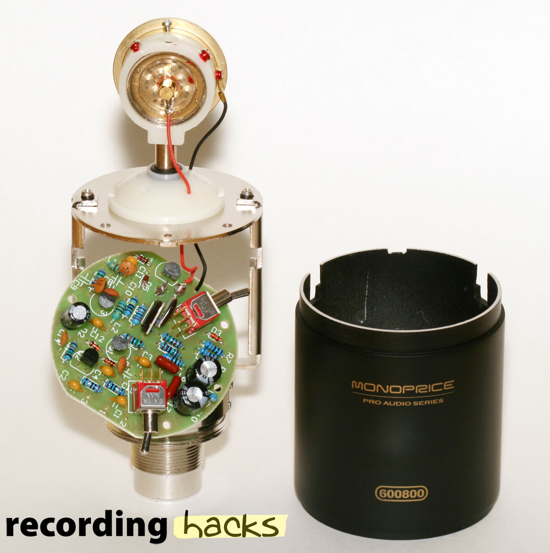
600800-pcb.jpg
 
damianschwartz said:
Finally had the chance to build my mics.

All went smooth thanks to all the info gathered during this time. Both worked at 1st attempt and everything seems fine.

However...
One mic sounds stunning, better than my friends original 84 (which is loosing lows due to age-capsule issues)
The other one has much more gain, like about 3-4 db more, and it's also darker, or with more bottom end, which could actually be just the proximity effect due to the higher gain. Swapped channels on the pre´s, same thing.

Not sure if this could be related to different fet betas, or the capsule. Bias went good on both units... Fets are supposed to come paired... any ideas?

These differences are identical to what I experienced. Try swapping capsules; I'm almost positive the tonal characteristics you're noticing will follow. The additional low end you're noticing out of the hotter capsule wouldn't be due to greater proximity effect; that's due to physical placement rather than output level.
 
Finished mine up! It's a pretty quick build if you know wtf you're doing (I didn't). Sounding all good from what I can tell! Thank you everyone for all the knowledge dropped in this thread, it was very helpful.
 
Banzai said:
If screws are all the way in you can pull the body tube off. Much easier to unscrew from just the connector housing.

Recommend replacing them with stainless steel M2x5. You can also just use a single regular M2 screw. Holds just fine.

I just received some M2x5 stainless steel set screws from McMaster Carr: the one I tried seems to be the proper thread, but sticks out around 2mm when fully screwed in and I don't like that.  Originally M2x3 were recommended and I believe I will like that a lot better.  McMaster Carr has these:
p/n 90251A151 Thread-Locking Cup-Point Set Screws, 18-8 Stainless Steel, M2 x 0.4 mm Thread, 3 mm Long, packs of 10--and I think they are going to be really great.  They have an imbedded nylon thread lock.  They also take a TINY Allen wrench.  The one I have that fits measures 0.87 mm, flat-to-flat, on my calipers.  It's like 1/3 the diameter of a pencil lead and you have to go to a fairly serious hardware store to get them.  If the new screws present any problem I will post about it. 
 
Back
Top