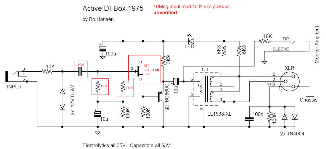
Bo Hansen DI layout

GroupDIY Audio Forum

Help Support GroupDIY Audio Forum:

This site may earn a commission from merchant affiliate links, including eBay, Amazon, and others.
After a couple of years of using this DI circuit with various transformer options, I now have a better opinion to share regarding the different possibilities.

Carnhill vtb9045- really shines on acoustic instruments that use a piezo pickup for live performances. There is drastic amount of clarity compared to the standard issue off-the-shelf options. Depending on the instrument and the environment, all that is required is a HPF and maybe some low mid cut.

Cinemag CM-9711 - I use this for anything that is a sample based instrument (keyboards, interfaces, drum machine, etc). For whatever reason, especially in a live environment, those type of sources are more easily heard in a thick live mix without the need to push them excessively loud. Typically for this application a passive Radial product (which are fine) is used, but when the dynamic of the music builds, things like keyboards tend to get lost, especially in a venue with subpar acoustics. This design plus the Cinemag seems to alleviate this problem. It even improves the clarity in IEM mixes and performers usually ask for less level due to being able to hear their sample based source better.

Sowter 91459045 - If it is a bass, I only use this. It's the more expensive option and requires a larger case, but I have never had a bass guitar have as much clarity from the top to the bottom of its range with as little processing than with this DI configuration. It gets noticed with other bass players and engineers, which is really nice because it allows me to bypass all the Avalon and other gear that you typically see in a bass rig that cause problems more often then they should.

I have built versions with Haufe and OEP transformers, but compared to the ones mentioned above they do not seem to do anything special that would make them better than a passive Radial or some other similar product, but are more convenient as they have a footprint directly on the PCB. I built these with the components and construction methods exactly as prescribed in the assembly instructions, and all of them are noise free without the need for a ground lift. If there was noise it was because the source was generating it and not the DI. I have not found any need to tweak the circuit for different transformers or incoming impedance loads.

Two things that would be nice is for the PCB are to have a couple more options to directly mount different PCBs like JLM does with his Baby Animal preamp boards and a readily available compact enclosure option with engraved I/O labels. But as far as the circuit is concerned I think it is perfect. I definitely think it belongs among the ranks of other revered classic audio designs.

It would be interesting to see results of using different transistors and other components for the sake of science, but for those contemplating building some of these I would say don't bother with trying to figure out crazy modding schemes and to save that time and energy for other builds.

Brilliant work, Mr. Hansen. Thanks for sharing your brain with us DIY peasants.

Thanks!

Paul

 
Paul,

Thank you for sharing your test results for different transformers, very interesting.

The types you mention as Carnhill VTB9045, the old Neve/Marinair mike-transformer workhorse, use to be a definite winner with its nice character.

And also Cinemag CM9711, (similar to Jensen JT13K7) with its wide bandwidth, low distortion, nice phase  and level headroom, is almost a theoretically completed perfect 5: 1 transformer.

But I'm curious about what you think about Lundahl LL1538 or 1538XL.

--Bo
 
Mr. Hansen,

I haven't built one with the Lundahl option. I initially went with Haufe's as it was reported how close they both were sonically in this circuit. I have about 10 boards left that I am going to use for something, so I may try the Lundahl's then. But as of right now I'm very happy with the ones I currently use, so further testing on my end is a low priority. Maybe that can be something to put on the list for later this year.

Thanks!

Paul
 
Sowter 9145 - If it is a bass, I only use this

Any bass players use Bo's DI with the LL1538 transformer?

Whats your experience, do you need to up the transformer to LL1538XL or even the Sowter 9045 for good bass?
 
Today I am going to write something about DI-box transformers, regarding choice of type, character and quality.
I do it from my own point of view and experience.

My DI-box design is especially optimized for the Lundahl LL1538 or 1538XL.
It therefore performs very well when the balanced XLR output is loaded with a normal microphone input on a mixing console or preamp, that have a input impedance of about 1-2 kohm.
It is also capable of driving  very long cable lengths such as a multi-cable/stage box.

The other two options Haufe and OEP I have also tested, both practical and measurable, so I'm sure they can handle this too, but the LL1538 is still the best in all situations.

LL1538 is one of the best microphone input transformers in the world right now, along with some other types from Jensen and Cinemag.

Lundahl's dual coil structure and winding technology without bobin and their own core material production is unique, giving very high quality especially on small signal audio transformers.

Ok, now we talked about high quality with a great bandwidth, low distortion and high level capacity.

However,  there is another aspect of audio transformers, and sometimes it is a wish that they reproduce a special character for a particular purpose, such as for a bass guitar recording, and sometimes this does not have anything to do with "good quality", but more about music kind, production and taste, which is equally important.

Many times we think that older transformers made in the 1950s and 60s sound nice, such as UTC, Peerless, Stancor, Triad, Danish JS-Jørgen Schou and many others.

Unfortunately, microphone transformers from this time were mostly made for tube amps (low imp. to grid) and had high turns ratio around 1:15 to 1:30.

These types are not particularly suitable for active DI-box electronics, which are usually a unity gain impedance converter, and because these transformers can have a loss of -30 dB, the output becomes too weak to be an active DI-box.
A suitable useful loss from input to output for a active DI-box is about -15 dB.

So old high ratio microphone input transformer fit much better for passive DI-boxes, where you are used to weak output, and want it to be so.
For example, UTC type A10/LS10 or A12/LS12 has the reputation to sound great on some bass guitars.

Why these old transformers sound different and sometimes have a charming character, probably depends on the winding technology and core material from the past.
There are other guys in this forum who know this better than me, for example, "CJ" who has picked apart and analyzed more audio transformers than most of us.

Of course there are a lot of brands and types of microphone input transformers with ratio around 1:5 and 200 ohm to 5 kohm, that will work ok in my DI-box, and many of them are also great and also have more or less character,  but I have not tested all of them in same way as I did with Lundahl, Haufe and OEP.

I have listed a number of possible types on my DIY page www.hansenaudio.se/techpage.htm and some I have tested, and some I have guessed are good for this application.

It's almost 15 years since my DI box design was published on this forum, when it was called ProdigyPro, and during this time, audio transformers have increased in their range in the market.

For a few years, a new caterogy of audio transformers has started to appear on the market.
These are microphone output transformers, where some types with lower turns ratio, are probably ideal for active solid state phantom powered DI-boxes.
But keep in mind, normally  these transformers are not encapsulated/shielded, so the DI-box case/box must be in metal, so the transformer does not pick up disturbing hum or buzz.

I have noted that Cinemag has some suitable types that are worth testing, according to the following types:

CMO-5/200-ct
CM-2422-H or L
CM-2461-nico
CM- 9711

Also noted that it sells some China-made microphone output transformer under different names, mostly copies of AKG and Neumann's well-known types.
How they are in quality, I have no idea, but I doubt that they can achieve the quality like Jensen, Cinemag, Lundahl, Sowter and  and some others with equal experience.

For the last 10 years I have served lots of China microphones, and those types that still have transformers, have not impressed me much.

--Bo
 
Bo Hansen said:
It is also possible to replace the first NPN transistor and replace it with an N-channel JFET transistor, such as 2SK30, 170, 246, 2N3819 or 2N4391, 2N5457  series, and then only replace the 1 Mohms bias resistor to 10 Mohm or higher if desired, without having to change something else.

But even this I want to test for you, so everything works as it should.

--Bo

Hi Bo,
How are you?

Did you have the time to try the 10Mega inout mod?

You solution of using a N-channel JFET transistor and just changing the bias resistor seems like a really nice idea, and simple to implement. I would like to try that out

thank you so much
 
Whoops,

Now I have checked the hi-Z JFET modification so it will work proper in my DI box design.

But I would also like to point out to others who read this post that in normal use with electric guitars, bass guitars and keyboards, it's my original design with 1 Mohms bipolar input, which among other things, is a bit of the sound and makes it different in its character from other active DI boxes on the market.

So this higher input impedance modification is especially intended for use with Piezo contact microphones for example acoustic guitar, string instruments or double bass.

The first thing to do is choose a N-cannel JFET transistor to replace the BC550C transistor on the input.

The best audio N-channel JFET transistor we've had in the past 30 years is Toshiba 2SK170GR or BL, and the best thing about it is that it fits right onto the PCB, where Drain will end up on Collector, Gate on Base and Source on Emitter.

Other JFETs that also work perfectly are 2SK30ATM, 2N5457, 2N3819, BF245A, but here you have to look up with pin-out as it is different on all types.

Of course there are lots of other JFETs that work in this simple design, but those I've listed here are a safe card, and are usually available.

The next step is to change the working point/reference 1 Mohm resistor to 10 Mohm or higher.
Also, change the input capacitor from 100nF/0.1uF to 10nF/0.01uF.

Now the last change that is to change the working point voltage divider to get a perfect symmetrical clip on the output.

This 100 kohm resistor that goes from plus voltage rail to the junction where 100 kohm and 10uF goes to ground,.
This plus side 100k resistor should be changed to approximately 110k if 2SK170GR or BL is used, and approximately 130k if other JFET transistors are used.

This is all that needs to be done, good luck with your modification.

--Bo
 
As analogguru posted

For higher input resistance you could change one or two few parts and bootstrap the input
Decrease the 100K emitter resistor for more bootstrap drive current balance that against hfe x emitter resistor value contribution to the input resistance.
Move the bottom of the 1uf cap to the first emitter(change value to what HPF response you want)
You do not need a JFET

https://www.diystompboxes.com/smfforum/index.php?topic=99139.msg868712#msg868712

Is an idea I should build. You could make the input resistance switchable
 
Bo Hansen said:
Whoops,

Now I have checked the hi-Z JFET modification so it will work proper in my DI box design.

But I would also like to point out to others who read this post that in normal use with electric guitars, bass guitars and keyboards, it's my original design with 1 Mohms bipolar input, which among other things, is a bit of the sound and makes it different in its character from other active DI boxes on the market.

So this higher input impedance modification is especially intended for use with Piezo contact microphones for example acoustic guitar, string instruments or double bass.

The first thing to do is choose a N-cannel JFET transistor to replace the BC550C transistor on the input.

The best audio N-channel JFET transistor we've had in the past 30 years is Toshiba 2SK170GR or BL, and the best thing about it is that it fits right onto the PCB, where Drain will end up on Collector, Gate on Base and Source on Emitter.

Other JFETs that also work perfectly are 2SK30ATM, 2N5457, 2N3819, BF245A, but here you have to look up with pin-out as it is different on all types.

Of course there are lots of other JFETs that work in this simple design, but those I've listed here are a safe card, and are usually available.

The next step is to change the working point/reference 1 Mohm resistor to 10 Mohm or higher.
Also, change the input capacitor from 0.1uF to 0.01uF.

Now the last change that is to change the working point voltage divider to get a perfect symmetrical clip on the output.

This 100 kohm resistor that goes from plus voltage rail to the junction where 100 kohm and 10uF goes to ground,.
This plus side 100k resistor should be changed to approximately 110k if 2SK170GR or BL is used, and approximately 130k if other JFET transistors are used.

This is all that needs to be done, good luck with your modification.

--Bo

Hello Bo,
thank you so much for taking the time to try that out and give me/us some feedback

I will try those mods, might also do some recordings with before an after, with some piezo pickups, so we can check and decide if it's worth

can you please just check if I understood everything you advised,
I changed the original schematic with the mod components in red

igZuyvR.png


Whoops,

Sure, you've got everything right.

Btw....
Depending on the type of Piezo pickup and if the length of the input cable allows this, you can change the 10 Mohm resistor to a higher value, (10-100 Mohm) without having to change anything else.

But I do not know if the two protection Zener diode on the input allows so much more than 10 Mohm (maybe someone else who knows, for example PRR) but if you only use Piezo pickups, you can remove these Zeners.

--Bo
 
Hi Gus,

Sure "Bootstrap" on a bipolar input is smart, but when you get up to 10 Mohm or higher, I trust more on JFETs or tubes because they are "natural" hi impedance on the input.

In addition, the 2SK170 has extremely low noise and is a nice JFET in many other ways, so for Piezo pickups this feels more right.

Btw, I know you like discussing microphones........

I could even imagine that this JFET modification on the DI-box electronics could work very well as amplifier in a capacitor microphone, if the 10 Mohms Gate reference resistor is increased to 500 Mohm or more.

Ok, it needs a step-up dc to dc converter for polarization voltage because the DI box electronics will draw 3,5 mA and it only stays 36 volt after the phantom feed resistors. or 24 volt after the phantom receive resistors.

Of course, it will be a 1:1 buffer amp without about 30dB gain which is normal otherwise, but as it will not drive a 9:1 transformer, it will be more like an AKG C414-EB/old.

--Bo


Bo Hansen said:
Sure "Bootstrap" on a bipolar input is smart, but when you get up to 10 Mohm or higher, I trust more on JFETs or tubes because they are "natural" hi impedance on the input.

In addition, the 2SK170 has extremely low noise and is a nice JFET in many other ways, so for Piezo pickups this feels more right.

Agree - Bipolar bootstrap is nice but has more to go 'wrong' in terms of frequency response anomalies etc so seems like making extra work compared to putting a JFet in there.
This may be stating the obvious but you'll have a hard time getting 2SK170 unless you have some already. LSK170 is equivalent from Linear Systems. Not sure how easy to get these esp if DIY. I sourced some a few years ago for a (non-audio) comercial project from Micross in the UK.
 
Newmarket,

Yes, those Japanese audio JFETs had amazing data about almost everything.
It was probably the 1970's HiFi industry that forced this development.

In the last 10 years I have bought so many N and P-channel JFETs I've afforded, so it has become about 5,000 pieces, a mix between brands like Toshiba, Hitachi and NEC.

Now I have JFETs for my future projects.

--Bo
 
Again as Analogguru posted

analogguru said:
BTW, I also doubt that it is really necessary to have an input impedance of 10M for a piezo pickup, especially when the pickup should have its on impedance converter [think about 5m cable from pickup to the DI-Box with 100pF/m {= 320kOhm @ 1kHz, 32kOhm @ 10kHz}], but....

It makes more sense to keep the input at 1meg or even lower and have an impedance converter circuit at the guitar or bass.  You could power it from the DI with a tip ring sleeve connection. Or even a two wire connection.
 
Back
Top