Bogen MXM Direct out Mod (attached schms in reply posts)

GroupDIY Audio Forum

Help Support GroupDIY Audio Forum:

This site may earn a commission from merchant affiliate links, including eBay, Amazon, and others.
rackmonkey said:
What's your source? Dynamic mic, ribbon, signal gen, etc?

BT

Heres what I Have.  I just ran a simple 1k sine through the unit via an insert in protools.  I set the signal generator to -20db level and used the +4db and -10db input option in the Apollo software from what i noticed setting the apollo to -10db setting yielded a greater level around 17db in gain through the unit and the +4db only gave me a 5db gain.  I have two images so the second will be in a new post!

Thanks,
Romp


Attachments

  • Screen Shot 2017-09-26 at 9.07.42 PM.png
    Screen Shot 2017-09-26 at 9.07.42 PM.png
    335.5 KB · Views: 9
So input to output, what does the mixer circuit look like as you have things now? There are several schematics posted. Do you have the stock MXM right up to the 12AU7? And did you end up using the output stage from the MXM-A that was posted earlier, or something else? Any changed part values? You mentioned maybe playing around with feedback. Did you do that? not completely sure what you're working with at this point.

BT
 
rackmonkey said:
So input to output, what does the mixer circuit look like as you have things now? There are several schematics posted. Do you have the stock MXM right up to the 12AU7? And did you end up using the output stage from the MXM-A that was posted earlier, or something else? Any changed part values? You mentioned maybe playing around with feedback. Did you do that? not completely sure what you're working with at this point.

BT

I changed some stuff around a little last night. I got more in the direction I was hoping for.  Im now at +20 db at -10 apollo level and +8db at +4 level.  I attached the schematic of what i currently have.  Changes i made are shaded green! Its very close to stock schematics.  No negative feedback. 

Thanks!
 

Attachments

  • Bogen Pre Schematic Rev 2.PDF
    43.2 KB · Views: 18
ruffrecords said:
Pins 7 and 2 of the 12AU7 have no dc path to 0V. You need to insert something like a 1Meg resistor from them to 0V.

Cheers

Ian

I see,  I was assuming that reference to ground would be the volume I have which is 500K  do i need the 1M in addition to that?
ROMP
 
ruffrecords said:
Pins 7 and 2 of the 12AU7 have no dc path to 0V. You need to insert something like a 1Meg resistor from them to 0V.

I'm betting that the pot has a connection to ground that's not shown on the schematic posted.

BT
 
rackmonkey said:
I'm betting that the pot has a connection to ground that's not shown on the schematic posted.

BT

Yeah, it does.  Its not in the schem. I have it right after the Ef86 output .1 cap.  I went with the typical ef86 volume value but would this need to be higher like a 1M?
 
If you're happy with what you're getting from it now, I don't think it's worth messing with. Just my 2 cents. Sounds like you got what you were after, so congrats. Have you done a sweep or even just a listening test? How's the response?

BT
 
rackmonkey said:
If you're happy with what you're getting from it now, I don't think it's worth messing with. Just my 2 cents. Sounds like you got what you were after, so congrats. Have you done a sweep or even just a listening test? How's the response?

BT

Thank you, Im close,  As far as the bare bone circuitry im happy. The freq response is dead flat when pushed with white noise.  I may try a 1m vol pot just to see what happens and I may try a negative feedback riff from the primary of the input transformer to the output of the EF86 but if i'm already skeptical with gain I may just leave it alone.


Thanks for all the info, BT

Romp
 
Rompstomp89 said:
I see,  I was assuming that reference to ground would be the volume I have which is 500K  do i need the 1M in addition to that?
ROMP

There is no pot in the schematic you posted.

Cheers

Ian
 
> There is no pot in the schematic you posted.

Agreed.

If done as shown, it will not be stable.

If it is stable, then it isn't built as drawn.

(Or something strange, like a just-so amount of leakage in flux-blob or damp wafer socket.)
 
You guys are right that he doesn't have the symbol in the drawing for a pot, but he has "Volume 500k" written at the point in the circuit where a pot is shown in the original MXM schematic he posted earlier. Based on that and the fact that he seemed to be getting stable operation, I assumed it was there and that he just didn't bother putting in a symbol for it for whatever reason. Assumptions in electronics - often a bad idea. But here we are.  :eek:

So correct, PRR - not built as drawn.

BT
 
rackmonkey said:
You guys are right that he doesn't have the symbol in the drawing for a pot, but he has "Volume 500k" written at the point in the circuit where a pot is shown in the original MXM schematic he posted earlier. Based on that and the fact that he seemed to be getting stable operation, I assumed it was there and he just didn't bother putting in a symbol for it for whatever reason. Assumptions in electronics - usually a bad idea. But here we are.  :eek:

Ha, yes, the volume pot is indeed in the unit and it is working wonderfully.  It is not in the schematic because I was using a cheap photoshop app and wasn't able to fully draw one very easily which is why I labeled it instead.  But youre right, Assumptions arnt always the best especially Since Im reaching for help with alot of people who know way more than me in this field.  if it wasn't for you guys I would be bald trying to figure this out myself.  So thanks everybody!
 
PRR said:
> There is no pot in the schematic you posted.

Agreed.

If done as shown, it will not be stable.

If it is stable, then it isn't built as drawn.

(Or something strange, like a just-so amount of leakage in flux-blob or damp wafer socket.)

yes, sorry. It is only labeled in the schematic because I was using a cheap photoshop app and couldn't figure out to properly draw one legibly.  It is however, in the unit.  Im using a 500KA pot at the moment and was going to try a 1M to see if it helped me get a tad more gain by taking signal further away from ground.
 
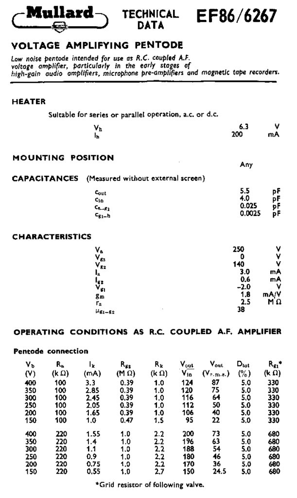
If you're still looking to squeeze more gain out of this circuit, rather than looking at the output stage, start by making sure you're getting what you can out of the EF86 in the input stage. The Tube Manual is your friend here. It's about the best tool to keep handy when you're building/modifying tube gear. I think this page is from the Mullard tube manual. It's a good idea to also keep a copy of RDH4 around (The Radiotron Designer's Handbook, 4th ed.). You can download a PDF copy from Tubebooks.org here: http://www.tubebooks.org/Books/RDH4.pdf

There's a table at the bottom of this page that specifies the various part values of an EF86 RC coupled amp gain stage. The Vout/Vin column is the gain you get with the values specified on that line. I think you were running B+ at about 350V, so look at the row with Vb at 350. Check your part values against those. Pay attention to Rg, which is what the grid leak resistor of the following stage must be for proper loading.

Meant to post this yesterday but time got away from me.

Ak1GykXh.gif
 
> a cheap photoshop app and couldn't figure out to properly draw one legibly

Don't blame tools. I'm using a OLD "cheap photoshop" (PSP 7.0.4); took 5 minutes to grab your image, grab a pot from Google Images, paste, *and* grab the app's Info screen to show how cheep I am. The actual pot-grab was less than half the time (PSP did not want to grab its own info screen).

That woulda saved several minutes of others' time pondering and typing about how it can't work when it does.
 

Attachments

  • Jasc-pot.gif
    Jasc-pot.gif
    15.7 KB · Views: 18
I just noticed you have a 620 ohm resistor across the grid of the EF86. The probably explains your low gain. Do you have the T157 input transformer fitted?? If you do then it needs loading with a much higher resistance, like 150K or more.

Cheers

Ian
 
I think I recall that he mentioned the T-155 rather than the 157, Ian. Same transformer with a 200 ohm primary rather than 50.  Loading requirements should be the same. I've used the 155 on another (non-Bogen) pre I built and loaded it with 256k. Performance is good with that load. I'm pretty impressed by all those silver-can Bogen inputs. Not so much the later black ones.

BT
 
rackmonkey said:
I think I recall that he mentioned the T-155 rather than the 157, Ian. Same transformer with a 200 ohm primary rather than 50.  Loading requirements should be the same. I've used the 155 on another (non-Bogen) pre I built and loaded it with 256k. Performance is good with that load. I'm pretty impressed by all those silver-can Bogen inputs. Not so much the later black ones.

BT

Ok, in which case the 600 ohms or so across the secondary is definitely wrong.

Cheers

Ian
 

Latest posts

Back
Top