[BUILD] 1108 DIY project and PCB layout

GroupDIY Audio Forum

Help Support GroupDIY Audio Forum:

This site may earn a commission from merchant affiliate links, including eBay, Amazon, and others.
OK jumping the gun a bit. Here is my preliminary BOM.

EDIT: Deleted this cause it is too confusing. Will post a good one soon. Mac already has a bom on page one I failed to notice. Sorry Mac!

John
 
What is the practical difference between the Input level pot, the pad, and the gain switch?

I'm not sure these will get much use in the situation where you need a lot of gain (which will be pretty typical with this amplifier because it is max ~40dB). But for a very loud sound source and a high level mic, having these options may be necessary.

The pad is before the input transformer, so it lowers the level hitting the input transformer, which can be necessary for hot signals, depending on the maximum level your transformer can handle without distorting.
The input level pot only reduces the post transformer level before the fixed gain amp as necessary. This is the main level adjustment for the preamp because it is continuously variable.
The gain switch increases the fixed gain of the amplifier by 5 dB in the high position. It may affect how the preamp sounds, but I haven't done any comparisons yet.

 
Good info DMP. In a situation with condensers in drum overhead situation the pad may be necessary. I am familiar with old UA stuff crunching under pressure. Not that they sounded bad. But needed some extra care in gain staging.

Some of the mics I use have massive gain on a loud source like a guitar cabinet. 40DB is plenty in A Lot of situations. And for other situations we all have other pres.
John
 
dmp said:
I'm not sure these will get much use in the situation where you need a lot of gain (which will be pretty typical with this amplifier because it is max ~40dB). But for a very loud sound source and a high level mic, having these options may be necessary.

The pad is before the input transformer, so it lowers the level hitting the input transformer, which can be necessary for hot signals, depending on the maximum level your transformer can handle without distorting.
The input level pot only reduces the post transformer level before the fixed gain amp as necessary. This is the main level adjustment for the preamp because it is continuously variable.
The gain switch increases the fixed gain of the amplifier by 5 dB in the high position. It may affect how the preamp sounds, but I haven't done any comparisons yet.

Thanks ;)

Anything that controls the input level will affect the output gain Tomas! LOL

You smartass  :)

BTW, which of those vactrols is suitable for this project?


Sorry Tomas didn't mean to be a smartass. LOL!

Waiting for parts like everyone else. Mostly the proprietary output transformer. I'll make a real bom when I try it. But this isn't paint by numbers on this.
I want it to sound like the real ones. The bom is just to get it to operate. And already changed it a few times...

So realistically there is NO bom......... Just a guess. So don't spend any money. My boards came today. Thanks Mnats!! CJ is now famous!  ;)
Putting parts into it now.... I don't let circuit boards sit around for more than an hour.

John

EDIT: BTW half watt resistors fit fine...
 
Small update on these things. Maybe I am just stupid but I finally wrapped my head around why this thing has an ldr in the first place. After playing with it. It is used as a remote control so you can adjust the volume of the pre from a mile away. Without running the actual signal to and fro. The LED isolates the control from the actual input signal. Keeps the signal flow on the card. Slap me LOL.

I think DMP has the ticket by just using a pot on the input. I'm not making an antique console...  Gonna play with that. But that vactrol would prolly be really cool for like a guitar compressor effect or something. I guess it would need some kinda buffer circuit or something to get the sidechain to that led. Seems very "guitar pedalish" LOL. I think a DI on it and a sidechain may sound really cool maybe...

BTW: I see on the schematics I have that the resistor across 5 and E is supposed to be 8.2k to bypass the equalizer. But Mako's schematic has 150k.

BTW2: you COULD use a leftover MNATS bipolar supply to power both 24 volts and 48 volts phantom. Just gotta mod it a bit I believe. Correct me if wrong... Owel sent me a 4448 five fish power supply for the Christmas thread a couple years ago. Been using it as a phantom supply ever since. But now I populated the other side of the board and is perfect for this.  I swapped the control resistor for 24 volts. Thanks again Owel!!

BTW3: if you use a 30-30 power transformer (I have a few) you can get 24 volts and 48 using the LM317's. Thought that I would need more than 30 but got full 48 volts from it. It's about 36 ac before rectifier. But a bit more than 30 would be better. (Avel Lindburg y236107 is what I used) With enough power to pipe voltage out the back to more of them. I know most people know this but just thought I would throw that out there. Some new experimenters are trying this. :)

I found a UTC 0-2 on Evilbay so have 2. This will be a vintage thingy. LOL! I am only putting 2 in a 1U cause we need to dissect that EQ ;) and will need room!

And one question for DMP did you slam the input with a loud condensor yet? Should I put a pad before the input transformer? I know you were using an Sm7 right? And one last question. I see a switch on your schematic Mako for the input transformer center tap. Is that just for like a ribbon mic input?

Thanks,
John


I see on the schematics I have that the resistor across 5 and E is supposed to be 8.2k to bypass the equalizer. But Mako's schematic has 150k.
The 8.2k is strapped across 5 and E externally, in parallel with the 150k. Refer to the manual for a more thorough description. I soldered these two resistors together since the first rev of the board did not have a better option.
did you slam the input with a loud condensor yet? Should I put a pad before the input transformer? I know you were using an Sm7 right?
I have used a condenser with them without needing the pad, but not with a really loud sound source as of yet.
An O-2 was spec'd to +8dBm I believe.

 
Thanks so much for the reply DMP. But still a bit confused for the 150k resistor. Looking at the 1.1 mnats schematic. I put 150k there or 8200? Or an equalizer!!!?

I have several shure pads so may not put a switchable pad before the transformer for now. And only 3 switches available per channel. But I am gonna diss the vactrol for now even tho I have them installed already.

Thanks again,
John
 
8.2k OR the equalizer are in parallel with the 150k. I don't know how to make it clearer. Maybe someone else can chime in if I am missunderstanding your question.
 
Sounds pretty clear. Just weird I would use a parallel resistor when I could just use ohms law and put the correct one there. That's why I am asking. Once again maybe a dumb question. And thanks again for the help. I appreciate it! Just waiting on out transformers...

John

EDIT: Actually I didn't realize I had already populated the 150k there is an extra spot for the eq on this board (Or 8.2k). Couldn't see the forest thru the trees on this LOL! Now to figure out how to put some kinda eq in there... Hmm Even if not the original one. Something simple.
 
Does any one have actual PCB dimensions of the self etch 1108 board given in Mnats .pdf  ?

When printing the .pdf , I can't tell if the size is correct , its seems a bit small when printing
at 100 % scale.

 
Had some time to knock out a prototype of my 1108 design last week.
Cant wait to test it out
I wanna throw a DI on the board since I have a little room left. any suggestions?

2011-01-27205500.jpg

2011-01-27205527.jpg
 
Woohoo finally have time to finish mine. Almost done. I stuffed a pair into a Hammond chassis. The thing is I only have 3 switches per channel. 1 for phantom. The other 2 I was going to use for pad and boost.

DMP after using yours is the boost useful? Or do ya leave it on all the time. Does it effect the sound much? Cause I could use 1 switch for input impedance maybe. Undecided about it. I definitely want the pad and phantom. But that last switch isn't wired yet. I always use cables for polarity. So don't need that. Not that I won't try it every which way lol. Just want a good starting point. I guess I could drill 2 more holes but ran out of switches...

The box looks cool so far. :) Anyone know where to get white datech dry transfers? I have black which doesn't help for a black face plate. Could only find red. No good either.

Thanks,
John
 
Dustbro Can't ya just blow right past the input transformer for direct inject? Or will it fry? Looks cool tho!
Maybe just stay away from a P-Bass with a built in preamp. :)

John
 
Quote from Avedis hope he don't mind. Is interesting:

Hey, I read this and wanted to add something to it... next thing I know it's a few paragraphs...

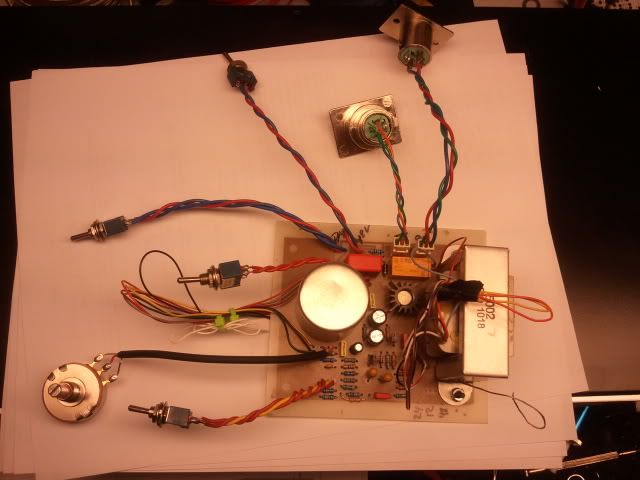
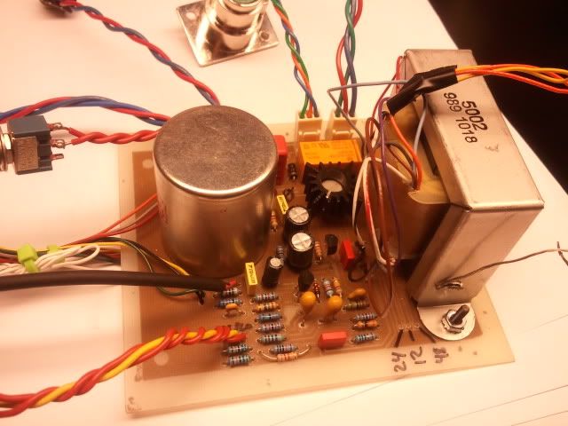
One day I was at Brent's rummaging through some plastic storage boxes (I love rummaging - I'm a rummager) and saw these 1108 amps lined up like bars of gold. The transformers looked of good quality, especially the mic transformer on the input. I found a schematic and some documentation on the uses and specs, so I took it home to study. I tapped the input transformer for a nice step up that added about 20 db's of gain (this is good because it imparts a character), it had adequate amp gain with low noise, and had another tranny in the output... all the right ingredients, I thought.

With the transformers step up and the gain of the amp, there had to be a reciprocal PAD on the input. After some testing I put a 20 db pad on there that matched the input impedance well and did a small mod on the amp to bring it in the gain range that was needed. Like other things I've worked on, I wanted to bring the 1108 to it's normal state of operation and meet the spec they were designed for; otherwise, a mistake in racking them up and you'll be hearing the character of the mistake more than the character of the amp. Some listening tests and realized it sounded good... different than what I'd heard in other pre's. It didn't have the huge low end I've been use to with other pre's but the mid and especially the top end of this thing was unbelievable. Equally interesting, from a technical point of view, is that a frequency response graph does not show any strong ringing or overshoot in the top end. hmm..

Because of the class A circuit, when you get to the max output (about +25dbu), the amp goes into asymmetrical clipping, meaning one of the waveforms clip but not the other which produces even-order harmonics. I'm not sure how it sounds because I never got to it (the power amp I had at the time clipped before many of these preamp did!) but you can put a simple three resistor pad inside an XLR to pad it down, say 15 db's, which may get it in the clipping range for you to use. This is cheap and easy and works better than potentiometer type attenuators, since pots have a tolerance and don't track perfectly at all points in reference to audio ground so you can kiss CMRR goodbye. Two series and one shunt resistor is all you need and you can solder it right in your XLR and label it, but you have to use metal-film resistors to maintain good noise rejection. Maybe I could put up a few pad examples on my site when I get a chance.

Anyway, I built the first prototype and took it in to Brent's for the rest to be prepared the same way.

I'd known that these amps came from Van Halen's old console when an API was put in so I talked to the great VH engineer Donn Landee about some photography work (he's an amazing photographer, too) and asked him a few questions about the old Universal Audio board. He gave me all the details on how they were used and how he had to use a makeshift PAD on them also, and was kind enough to sent some old photos of the board so I could see about getting that light tan color in power-coat finish. Growing up on VH in the 80's, and having an older brother yell at me for not handling the records to his liking, it was great to be doing this and talking to Donn Landee.

Since all that what was needed was a gain pot, PAD, phantom, and phase, I thought I'd keep it simple and easy for everyone and use the same faceplate the 312/312A had, but use a deeper chassis as the 1108's had fairly long frames. It also runs on 24vdc, so the already available BA/Neve type remote supply would work well. When they were done, one was sent off to Donn to photograph and he opened it up and liked what he saw and took some photos of the insides... but mentioned that they were mistakenly screened as UREI instead of Universal Audio. That was my fault... daammmitttt!

Avedis
 
DMP after using yours is the boost useful? Or do ya leave it on all the time. Does it effect the sound much?
I have mostly used this with the gain switch up. I haven't noticed a difference in sound with the switch in low, but I don't have the best ears.
 
Thanks. :) I put posts on the board for a movable jumper for the hi low. Just finished the pad wiring point to point. I made it 20 DB. Working on the phantom switches. Thinking of the impedance switch I was gonna do 500 ohm and 200 ohm. Think I should do 500 and 50? This is all just for starters. Those switches are a bastard to wire lol. I need new eyeballs. :)

Fires up with no smoke. The out transistors get the correct temp. So "Maybe" it will work hahaha.

John
 

Latest posts

Back
Top