[BUILD] 1108 DIY project and PCB layout

GroupDIY Audio Forum

Help Support GroupDIY Audio Forum:

This site may earn a commission from merchant affiliate links, including eBay, Amazon, and others.
Thinking of the impedance switch I was gonna do 500 ohm and 200 ohm.
Interesting - I only used the 500/600 winding. I'm curious if you find it useful. Are you trying to get different amounts of voltage gain, or suit different mics?
 
Some preamps have adjustable input impedance. It helps depending on the mic you use. Especially a ribbon mic. I don't use ribbons at my place tho cause I am sure they would get broken lol. And flipping the switch does change the sound somewhat regardless of the mic. Well 97% done still contemplating those switches. Only thing left...

The funny thing is even tho the actual boards are small this 1 U case is pretty busy inside. Can't believe ya squeezed that on a 500 card! Good job man.

John
 
Ok finally done. The pad switch was a nightmare to wire. I also have the phantom going there. Looks easy on a schematic LOL! I spent more time wiring those switches than the entire rest of the project!
I have 500 ohm and 200 ohm impedance switch, Phantom and 20 db pad. And a jumper "On Board" for boost. I have room on the faceplate for the boost switches. But saving it in case I want a 1/4 jack for DI.

I woulda etched a board for the switches if I knew how hard it was gonna be to P2P that. But done and looks badass! I would send a pic but my X stole my camera but have another on order. Pic soon. NO WAY I could fit an EQ in this box now. But it has a 1 amp power supply so could pipe voltage out the back to the EQ. Hopefully we can figure that eq out somehow! But the EQ looks passive so no power needed?

Does it work? Dunno yet almost afraid to try with all that wiring. LOL! Let ya know... My typical layout everything crushed to the left PT on right.

John
 
Well I tried it today finally! It works!! But I am not sure how to ground this thing. I tried a couple ways and I get hum or oscillation or white noise. And the hum is actually worse with the lid on LOL. I can get rid of 2 of them but not all 3 at once. Any suggestions for a grounding scheme? Turning the transformer made a big difference.

Thanks,
John
 
Use shielded wire, connect the shields to the case (chassis ground). Do not connect shields to the audio ground (0v). Connect the audio ground to the chassis ground at one point in the PSU.
Post a picture for more help.
 
OK I got 98% of the hum gone. It only hums a little with dynamic mics. The condensers work perfect. The first pic is BEFORE I put in shielded cables and the xlr grnds. It's got PLENTY of gain. I can bury my converters at 1/4 throttle with a Cad m179 test mic. One of the UTC's had a stripped mounting hole so I clamped the pair together. Here is some pics:

11081.JPG


11082.JPG


11083.JPG


11084.JPG


I have all the xlr grnds going to the power supply board. Where should they "REALLY" go?

Thanks,
John
 
OK I axed the wires from the PS 0V. I have all the xlr's to chassis grnd. I have 1 wire from 0V at the ps to chassis grnd at the input chassis grnd. Won't work at all without that. Sounds great with condensers! Till I try to put the lid on. then get a slight buzz. I read the Rane site again. And did it like that.

I even put the PT in an MU can. Turning the PT makes a HUGE difference even with the mu metal. Wierd... Maybe I should kill yje impedance switch and go direst... But seems like it has to do with the power supply. If I turn phantom on with a dynamic in I get a big hum...

John
 
Your build is looking great and you're almost done.
Doublecheck that your chassis is grounded together completely with a multimeter. The faceplate, bottom, sides, XLR pin 1s, etc... should all have conductivity to your chassis ground screw. I usually tie xpr pin 1 right to the chassis lug on the XLR and don't have problems, but going over to the chassis ground point is fine. You need 0V connected to the chassis grnd for you mics to have phantom power, that's probably why it didn't work at all without that connection.
Also, best orientation for transformers to minimize hum pickup is for their axis to be at right angles, not directly aimed at each other. Right now you inputs are in parallel with the PT. It would be best to rotate the UTCs so they are on pointing at the back of the case so they are at a right angle with both the outputs and the PT. 
Also, tightly twist the wires going from the UTC to the impedance switch if you haven't put shielded wire in there yet. You may want to try disconnecting leads there to see if that is where it is picking up hum. (try the preamp with the impedance switch in one position and disconnect the other two leads to the UTC). Tightly twisted wires pickup hum as 'common mode', which the transformer rejects.
Finally, if you're lucky enough to pickup a pair of UTC O-17 cases they provided mu-metal shielding to the input transformers. I've been trying to find these myself however for a few months, and haven't had any luck.
Next time consider doing an external PSU. I've started doing that on all my preamps.
 
Also, is the shielded wire going to the gain pot grounded correctly? I see three wires coming out of it to the pcb, but I don't see if a shield is connected to chassis at the other end. This is the MOST susceptible place for preamp to pick up hum, because it is carrying the unbalanced input signal to the preamp.
If you want a top notch piece of recording equipment you can't cut any corners on the wiring & grounding.
 
Thanks DMP for the suggestions. I did check the chassis parts first thing and the whole unit conducts. I tried bypassing the impedance switch on one channel with all shielded wires. No difference. I DON'T have chassis grnd on the pot wires tho. I am using mogami console wire with only 2 conductor and shield. Gotta search around my place for some 3 conductor. I'm away on a job but will be back to get this fixed tomorrow. It does sound Really good tho. I am very happy with it.

It's a five fish power supply. I just changed the resistor.

Thanks again,
John

EDIT: I searched everywhere. I know I had some 4 conductor foil shield cable somewhere. Musta used it all so stuck for now 'till I get some more cable for those pots. Either that or put the vactrols back in. I suspected there was a reason for them LOL. To keep the signal on the board.

 
I would call Cinemag or email them and ask what zobel parts are required. Just in case. But the rest should be the same.

UPDATE: I did finally get back to this project. I got some Mogami quad console wire from Redco for the pot wires. And ran shielded wire for everything off the board. I removed paint behind the front panel to ground the pot enclosures. Now I got a working preamp for condensors!!! I can put the lid on with no hum!

As DMP stated tho I wouldn't have ANY trouble prolly with an external Power Supply...

Still have a couple issues. If I use a dynamic mic it hums even getting the lid close to it LOL! And nasty hum if phantom is engaged. But I only tried an old EV mic on it to test. I think my phantom supply needs some work. My Eisen pres have a 47UF electrolytic and a .1 bypass cap from the phantom resistors to ground. Do I need that? I even tried a new power transformer same deal. And channel 2 is noisier even tho the wires are shorter...

Also the 1 meg pot is real touchy. I achieve max gain at about 1/3 throttle. Need to work on that. The original has a 1 meg resistor across the input iirc? Will try that. And another tip: 20 DB pad is TOO much! 10 DB is prolly better.
It doesn't seem to overload on loud sources as I had thought it might. Maybe no pad is required at all. But didn't try drums yet.

But it sounds great! Thanks Mnats. Just a little more experimenting left. And learned a bunch. Thanks for the tips DMP! Having fun with my MNATS 2-1108!!!!

It doesn't sound dark at all. Sounds totally high end. Kinda surprised with those antique UTC's. Gotta test it some more tho obviously. And best of all none of my friends have one of these. They are all gonna make me bring it with when I go back to NY. LOL

John

EDIT: OH and the impedance switch does work. It changes the sound somewhat. On a CAD m179 it gives it a slight bass roll off and a little softer in the highs. But on that mic 500 ohms sounds beefier. And this has plenty of gain for a condenser with lots of room to spare. Fear not... LOL

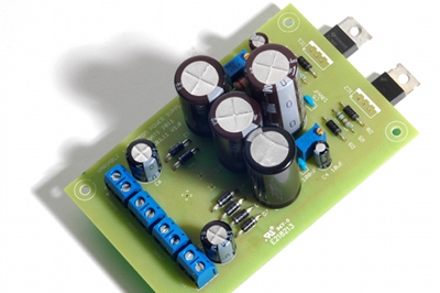
Horrible pics I know... My camera was stolen and got a cheapey for now to tied me over. This is what it looks like now:
IMAG0107.JPG


MU can:
IMAG0108.JPG


zmgwg said:
should I change anything in bom if i'm building it with cinemag 2511 on input?

In series, it's the same ratio as the original 1108 input (1:10).

I would keep everything the same to start and as John stated adjust the zobel if you feel the need.
 
I've created a power supply board for this project. Self etch files here: http://mnats.net/adjustable+phantom_power_supply.html or you can purchase boards from my White Market thread: http://www.groupdiy.com/index.php?topic=33604.msg410766#msg410766
 
Has anyone built the new Mnats power supply board for theirs yet? Mine doesn't seem to work. I have all the parts in correctly but have no voltage coming from either rail. I got 36 volts AC going in to the 24ac inputs from 2 different windings from my toroid. And when I check across the 2200 uf cap I get like 2 volts. I replaced the rectifier diodes and same thing. I used 4007's on the whole thing. Tried 4004's too for the rectifier and same thing. Nothing on the board even gets warm.

Thanks,
John
 
Stagefright13 said:
Has anyone built the new Mnats power supply board for theirs yet?

I guess you mean anyone but me? The board shown on my site was built from the same PCB batch from the one you received.
variable+phantom_board_completed_small.jpg


Stagefright13 said:
I have all the parts in correctly but have no voltage coming from either rail.

If you look at the schematic there are two supplies that are completely independent of each other built onto one PCB so unless the transformer is faulty or not connected to the board properly you have two circuits each with one or more of the usual faults. Start with one until you've fixed it before working on the other.

Stagefright13 said:
And when I check across the 2200 uf cap I get like 2 volts.

Remove the capacitors and regulator to eliminate them as factors and measure the output of the rectifier circuit. Wrong voltage there means the diodes are faulty or inserted incorrectly.

With a nominal 2 x 25V 15VA transformer and a 500 ohm load on each rail I get...

Adjustable supply: 29.4VAC input, 36.9VDC across the bulk filter cap and an adjusted 24VDC out.

Phantom supply: 27.6VAC input, 67.2VDC from the voltage doubler, 62VDC after the RC filter into the regulator and an adjusted 48 Volts out.
 

Latest posts

Back
Top