[BUILD] 1176 Rev A - Back to the beginning...

GroupDIY Audio Forum

Help Support GroupDIY Audio Forum:

This site may earn a commission from merchant affiliate links, including eBay, Amazon, and others.
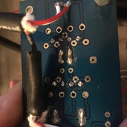
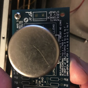
So i followed the signal to the input transformer pcb. going into the board, i can perfectly see the sine wave but after the input transformer it's completely gone. so there has to be some issue with the signal flow. i already asked for help populating this pcb but it seems nobody has this revision.. i put the jumpers in like in the description. is my input transformer broken?

 
TillM said:
You can test it on pin 1/4 and 5/8 one side should have circa 13 Ohm and the other 52 Ohm.
You don’t have to turn on the unit.

already did that. 13,0 and 50,9 ohm
 
scott2000 said:
Sorry if it's been mentioned before but what transformer is this on the input? ......

thats the ALTRAN C-3837 from hairball audio (https://www.hairballaudio.com/catalog/parts-store/audio-transformers/c-3837-1-input-transformer)
 
post number 630 here mentions something interesting.......

https://groupdiy.com/index.php?topic=20058.620


he said there's talk about this somewhere earlier in that thread as well...but I didn't see anything other than mentioning of t pad.... kinda confusing...


so are you getting signal to the actual pins of the input transformer...??
 
i got the first problem solved, it was a bad solder point, now i can trace the signal until the main pcb and input and output pots work fine but the overall signal is a bit low and the attack/release/ratio/meter switches/pots don't seem to work.  The meter driver and GR control amp don't show any signal. Only the amp section does.
 
scott2000 said:
is this your version??

https://www.hairballaudio.com/blog/resources/build-guides/wiring-your-compressor-

generally yes, but i am building revision A (the guide is showing rev D)
here are the guides i used: http://mnats.net/1176_revision_a.html
(new version: http://mnats.net/1176_reva-d_hairball_wiring_attack_release.html)
but i don't use the classic push buttons for ratio but the rotary switches

i made a rough schematic for you (hope it makes sense..)
 

Attachments

  • schema.jpg
    schema.jpg
    614.3 KB · Views: 6
Yeah thanks.... I read this on the g1176 rotary page....not sure if it's relevant to yours....

output pot

In the rotary version, the potentiometer is wired to the ratio switch board, which in turn is wired to the main board. The reason for this is the rotary ratio switch circuit requires an electrical connection to both the potentiometer and ground. Wiring the pot to the ratio board is one way to accomplish both goals.

http://mnats.net/1176-wiring-rotary.html

it mentions in the guide you linked that  the wiring is the same for the G1176 rotary and A aside from a couple small things......

here...

Generally, wiring the Revision A is the same as wiring a rotary version of the G1176. One subtle difference is that the GR (Gain Reduction) meter setting doesn't ground one terminal of the VU meter in the discrete version as it does in the IC circuit and special rotary control PCBs have been designed with this in mind.


maybe check out the G1176 rotary guide for a bit??? I'll look into it more..... quite a bit going on.... you'll get it....getting close for sure
 
you are right, i'm sorry, it was a mistake in my drawing. got late yesterday  ::)
i corrected it
 

Attachments

  • schema.jpg
    schema.jpg
    651.8 KB · Views: 11
scott2000 said:
Pretty vague drawing when trYing to see any errors in the ratio board etc......

Is this drawing of the boards relevant to what you have???

yes, exactly what i did! i already had a closer look into the gyraf version and tried to use that guide (http://mnats.net/1176-wiring-rotary.html) but there are some major differences on the pcb
 
So you have a bit of a Frankenstein.....

Rev D input transformer board.... G1176 rotary board......And a version 1.0 main pcb for the rev A????? is that right????

Can you specify???? Maybe link to each board you are using....even the metering???
 
scott2000 said:
So you have a bit of a Frankenstein.....

Rev D input transformer board.... G1176 rotary board......And a version 1.0 main pcb for the rev A????? is that right????

Can you specify???? Maybe link to each board you are using....even the metering???

no no.. the pcb's i use all came from hairball audio. you can choose between rotary version and push button version. everything is Rev A, everything is Hairball/mnats version (v1.0 from 2008).

here you find the boards: https://www.hairballaudio.com/catalog/parts-store/old-style-fetrack/mnats-revision-a-blue-stripe-boards#tab-75

Meter: https://www.ebay.de/itm/251620496234 (currently not the problem)

Just the wiring itself is not self explanatory because on the mnats website they use a gyraf pcb to explain the wiring procedure. that's somehow confusing me and maybe that's where the error sits..

i rewired every pot and connections from and to the meter and ratio boards. i got no clue where else to look.
I already successfully built the Rev D with push buttons but this one is giving me a hard time.. :(
 
Oh ok thanks.....


I'll try to decipher some things and see if I can draw up something I think I might do if I were using these boards just to compare.... 

So those ratio rotary and meter boards are exactly the same as what you have????  I know you have the version one main pcb....
 
scott2000 said:
Oh ok thanks.....

.... So there is no issue using a 100ma meter as opposed to a 1ma like is being sold on the site???

I'll try to decipher some things and see if I can draw up something I think I might do if I were using these boards just to compare.... 

So those ratio rotary and meter boards are exactly the same as what you have????  I know you have the version one main pcb....

oh where did you find that?  :eek:  but even using the 1mA HUTCO meters it didn't make any difference.

no they are also from '08, the ones online are the latest from '10. can't see any difference though.

thanks again !
 
Just looking through I have a feeling, just like you,  that the differences in the guides and the boards you have is going to make things tricky..... The pad designations are not the same in the rotary instructions...I think they seem quite different from what I can see so far......... I wonder if you'll have to make your own connections to the board, not paying attention to the pad numbers......

I'm surprised nobody has done it this way before that could help with some direction but it'll get figured out......

 
scott2000 said:
Just looking through I have a feeling, just like you,  that the differences in the guides and the boards you have is going to make things tricky..... The pad designations are not the same in the rotary instructions...I think they seem quite different from what I can see so far......... I wonder if you'll have to make your own connections to the board, not paying attention to the pad numbers......

I'm surprised nobody has done it this way before that could help with some direction but it'll get figured out......

exactly what my problem is..  am i the only one who got stuck..?!
 

Latest posts

Back
Top