You are using an out of date browser. It may not display this or other websites correctly.
You should upgrade or use an alternative browser.
You should upgrade or use an alternative browser.
[BUILD] 1176 Rev A - Back to the beginning...
- Thread starter mnats
- Start date


Help Support GroupDIY Audio Forum:
This site may earn a commission from merchant affiliate
links, including eBay, Amazon, and others.

scott2000 said:So here's what I have for the pots so far.....does this seem right to you????
yes that's correct. like in my unit
scott2000
Well-known member
Well this guy did a rotary and seems to have connected everything normally...so maybe it will be good in a bit..... I Need to read more......
#2658
https://groupdiy.com/index.php?topic=29981.2640
#2658
https://groupdiy.com/index.php?topic=29981.2640
scott2000 said:Well this guy did a rotary and seems to have connected everything normally...so maybe it will be good in a bit..... I Need to read more......
thanks for the find. i'm gonna compare.
Okay i can't really see any big differences except, he didn't wire the ground next to connection 7 on the left side of the main pcb (coming from ratio), instead he wired ground from the meter board next to connection 22 on the main pcb. i just used the shield from the cable and made that connection, didn't solder it to the meter board. but that wouldn't cause my problem would it?
scott2000
Well-known member
Maybe? I haven't looked until just now..I'll try to get into it more in a bit.. What are you doing with pads 18 and 20 too?...
Really wish I had one of these to make it easier to help you but you'll get it....
Really wish I had one of these to make it easier to help you but you'll get it....


scott2000
Well-known member
ok....hard to tell from this pic.....I'll try to draw some more out in a bit if I can....
it almost looks like the pad designation numbers may be the same but, if you look at the circuit, they are different......like pad 28 and 29 on the rotary version main pcb is quite different but, in that one build, he put the meter there like the instructions say.....
it almost looks like the pad designation numbers may be the same but, if you look at the circuit, they are different......like pad 28 and 29 on the rotary version main pcb is quite different but, in that one build, he put the meter there like the instructions say.....
Attachments

scott2000
Well-known member
Ok...sorry....had a red slurpy on white berber carpet fiasco I had to take care of........
I tried tracing what tata had going on in that picture..... the only thing I'm not sure of is the attack ,release and output pots.....they look different in his set up............but I just left those how I had them from the 1176 rotary instructions......
I wonder is he's active here still....He seems pretty into these things........
Anyhow, I've attached what I think I saw..... Don't take it as a final...There may be/must be errors..... But hopefully it'll get the ball rolling.....I'll look at your pics later.....
Attachments

wow thanks for your effort, man!
regarding the questions: i guess they are all grounded to chassis as well and the output xlr also connects to the output TX, so what you did is correct! Output, release and attack connections are actually quite easy to decipher with the mnats/g1176 guides. don't think i made mistakes there - anyway, definately gonna buy you a coffee if this works
regarding the questions: i guess they are all grounded to chassis as well and the output xlr also connects to the output TX, so what you did is correct! Output, release and attack connections are actually quite easy to decipher with the mnats/g1176 guides. don't think i made mistakes there - anyway, definately gonna buy you a coffee if this works
scott2000
Well-known member
No problem....Like I mentioned earlier, it pretty much looked to me like he just painted by numbers but I could certainly be mistaken...... I was reading so many different guides I don't know what to think....lol
I just quickly looked at your pics....I haven't followed anything but it wouldn't surprise me terribly if you had some solder bridges or cold joints.???...
Could be pics though.... Let me know what you find out.......I'm sure you're getting close.....
I just quickly looked at your pics....I haven't followed anything but it wouldn't surprise me terribly if you had some solder bridges or cold joints.???...
Could be pics though.... Let me know what you find out.......I'm sure you're getting close.....
scott2000
Well-known member
weiss said:already resoldered every point, didn't change anything. I can't spot any bridges but i'm gonna check everything again.
So you think you have it wired like tata's build?
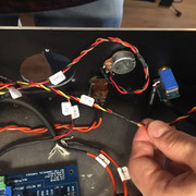
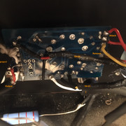
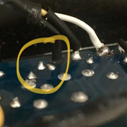
Hard to see everything as a whole from your pics. Do you have a big bird's eye shot like in tata's build?
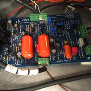
But regarding things like solder bridges, like here next to pad 18 on the ratio board, it looks like it could be one. Could be the picture though. I like to dip a soft toothbrush in some IPA and go over things. Then I find that some 2.5 reading glasses or similar helps me see things close up with some good light on things.... And using flux before soldering seems to keep things tidier for me and avoids bridging usually....even though the solder has it in it, the extra seems to work for me....not saying you have any bridges, just saying....
it's easy enough to check for continuity on some questionable solder areas to make sure none are touching where they shouldn't be....
Attachments


scott2000
Well-known member
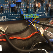
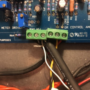
Do you have a better shot of the meter board....what's going where???
I feel bad with all of these pics :-\ I guess erasing them after a while wouldn't be a bad waste of space......
and it's hard to tell what you are doing with your output xlr...... Like in tata's build, he split right at the xlr I think??..to the opt and to the meter board......yours I guess splits somewhere too but I can't tell what's what..... All those color changes......
i know it's extremely confusing but i kept to the guide of mnats. mine is splitting a bit further from the xlr but it's still the same wiring scheme. they meet in some kind of star configuration and go to the output together.
i'll delete the pictures in a bit (although i think the provider does cleanings himself after some years) .
meter board is attached
i'll delete the pictures in a bit (although i think the provider does cleanings himself after some years) .
meter board is attached
Attachments

scott2000
Well-known member
weiss said:meter board is attached
Yeah that looks right....... Hmmmmm....
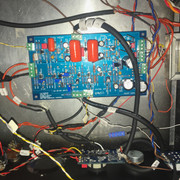
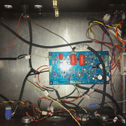
Can you post one big, clear, bird's eye of the unit as it is now???? I think the last set of pics were good but, they didn't show everything together as a whole...... With those and one more shot of the entire thing, maybe something will stand out......???
I've got a couple good shots of your entire build but, those are older pics and I'm not sure they are relevant at this point??
scott2000
Well-known member
Maybe you could check for continuity while referencing the test points on the schematic????
Like.....check from pad 18 on ratio board to wiper of q bias pot (r59) on main board
pad 29 on meter board to q13 collector on main board..etc......
Like.....check from pad 18 on ratio board to wiper of q bias pot (r59) on main board
pad 29 on meter board to q13 collector on main board..etc......
Similar threads
- Replies
- 3
- Views
- 438
- Replies
- 3
- Views
- 362