


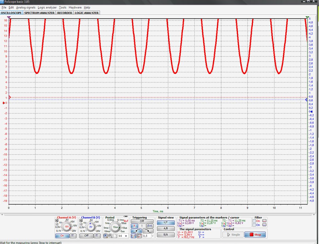
Also, this is the shot after the output transformer..
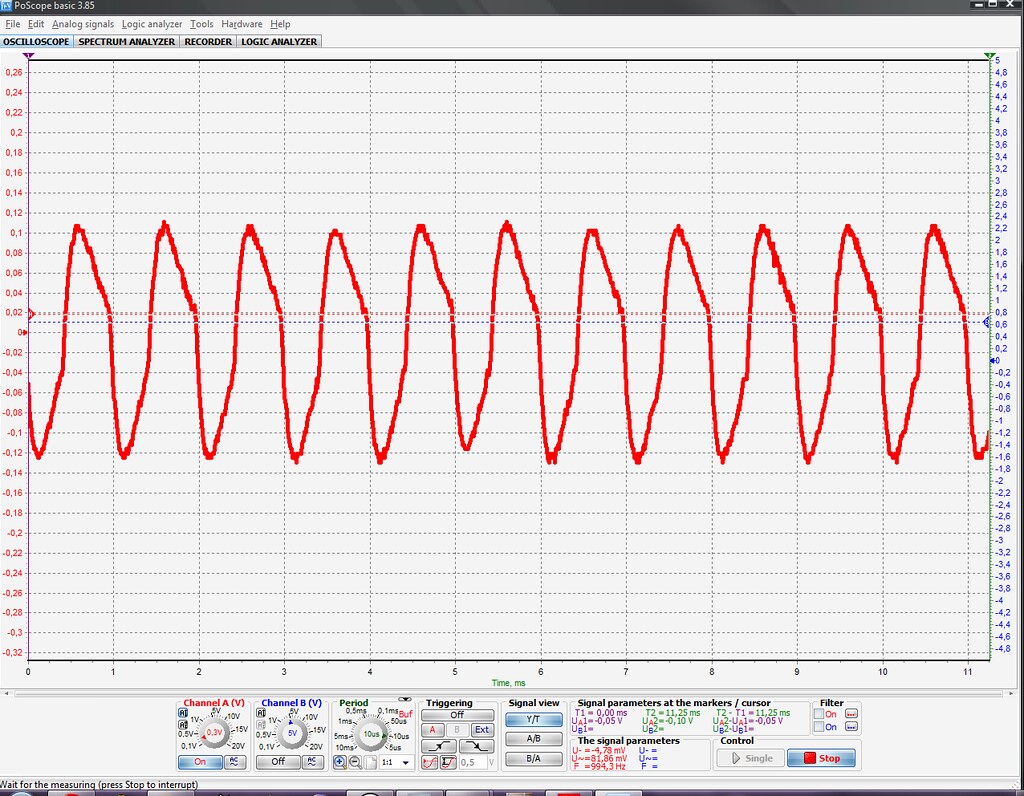
A tech friend of mine thinks I might have the OT wired wrong and/or am presenting wrong impedance to the output section.
I have a board marked V1.1 31.01.2009 and the OT from hairball's shop. Am I correct in assuming that:
- the colour codes printed on the board are the same as the ones on the OT
- output transformer orange and yellow wires must be joined together
- the red wire from the OT goes to the pin 2 of the XLR out and to the X pad of the meter PCB
- the blue wire from the OT goes to the pin 3 of the XLR out and to the Y pad of the meter PCB
are these assumptions all correct?


")