beaversaber
Well-known member
- Joined
- Jul 22, 2009
- Messages
- 72
isn't that what the bypass switch does? shorts 22 to ground?


evilcat said:I don't know, certainly. But if you do it with the switch, you disable the vu-meter. As you need it for the calibration, you have to do it manually with a wire.
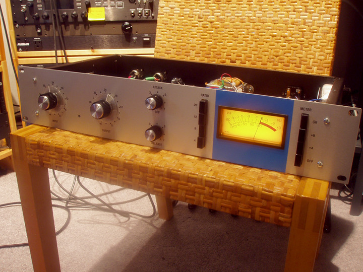
jordan s said:The input stage is highly susceptible to clipping when gain reduction is bypassed. When I'm compressing, it sounds great, then i bypass and it's clipping like crazy and I have to turn down the input knob. Is this normal?
jordan s said:Also, I was trying to find a good point to draw current for my meter LED and noticed that when measuring across R87 (between the out and com of the voltage regulator) I only get around 14V DC. I'm also measuring 15V at the input. I measure the power transformer putting out about 15V AC, did I wire this incorrectly? On the primary I have brown at hot, blue at cold, grey and violet tied together. On the secondary I have red and orange tied together at CT and yellow and black separately at the AC pads.
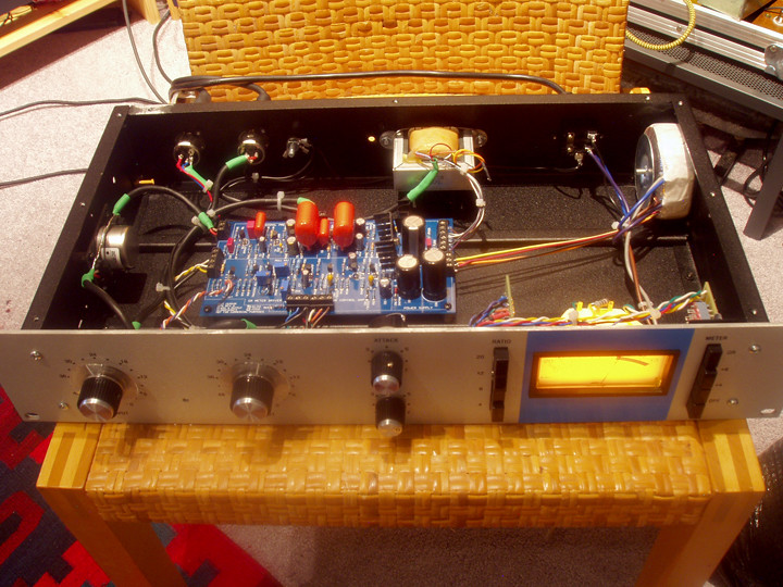
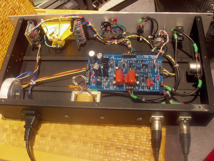
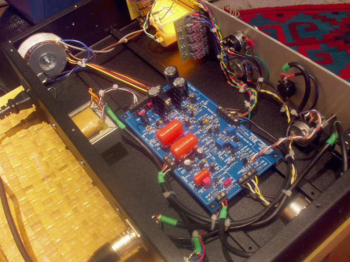
Echo North said:If your Q Bias is correct and your not seeing compression when you measure the output I would think you have a bad component somewhere in your GR section.
Check the transistor voltages in that section. If your voltages are odd, check the resistor values, check for solder bridges, change out the transistors...
Geoff's page is for the J board, but it still applies:
http://www.axtsystems.com/index.php?option=com_content&view=article&id=57:1176lnproblems&catid=34:1176ln&Itemid=62
Mike


![Soldering Iron Kit, 120W LED Digital Advanced Solder Iron Soldering Gun kit, 110V Welding Tools, Smart Temperature Control [356℉-932℉], Extra 5pcs Tips, Auto Sleep, Temp Calibration, Orange](https://m.media-amazon.com/images/I/51sFKu9SdeL._SL500_.jpg)


