[BUILD] 1176 Rev A - Back to the beginning...

GroupDIY Audio Forum

Help Support GroupDIY Audio Forum:

This site may earn a commission from merchant affiliate links, including eBay, Amazon, and others.
Nice!  Glad she's working!

The rear panel is actually flipped the opposite way and the input transformer is on the opposite side from the design.  Not a big deal and the case can be set up a number of ways, but it means the input signal has to cross the length of the enclosure a couple of times.

Recommended layout can be found here:
http://hairballaudio.com/enclosure/

Thanks!

Mike
 
One thing I'd like to note for others building this is that the zero adjust pot in the BOM with mouser part numbers has a shaft that is too long to fit on supplied mounting with the front panel. I had to use two of the stand-offs that were supplied for the input transformer. Then it was a perfect fit!
 
Yes true.  The zero adjust standoffs were designed to handle shorter pots since people like to use some over others.  Easier to make a spacer for longer shafts then add length to shorter ones (that sounds dirty).  For the one in the BOM I just add an extra nut behind the bracket to provide the space.  But I happen to have an endless supply of those laying around.

Mike
 
Now the only question is, do I build another Rev A to make a stereo pair or do I build a Rev D to have a different color?  ::)
 
Quick Q on Grounding:

The mnats page shows the Input XLR shield tied to chassis ground - which goes directly to the PCB and has a pad for the shield (and serves as the single junction point of Signal and Chassis ground).

1176_wiring_input_jack_thumbnail.jpg
1176_wiring_input_header_thumbnail.jpg


The Hairball/mnats Rev A 1.2.5 kit has the XLR Input going to the Attenuator, then Input Transformer, then PCB Input (as a 2-conductor input from the transformer - no pad for the shield).  This means the Audio/Chassis shield never connects to the PCB at the input pads.

Where is the best place to tie Chassis Ground to Signal Ground then?  It would seem that passing the chassis ground through all that wire (XLR > Attenuator > Transformer > PCB) would add some slight resistance versus a shorter run from Chassis > PCB.

I have the AC Ground tied to the chassis at the IEC connector (scraped the paint off the chassis - it's solid).

And I'm assuming it's a good idea to keep the shield continuous from the Input XLR > Attenuator > Transformer > PCB?  And then should I still tie this balanced input wire to the chassis at the XLR Input and leave it "floating" at the PCB side (as the pic above would suggest) - or should I float the shield at the Input Jack and terminate it wherever the Chassis ties to Signal ground (if using a different ground point based on the above question)?

Just want to make sure I don't create any ground potential issues.  I'm taking my time with hopes of a perfect pair of units :)

Thanks  8)
 
You need to carry that shield from the input xlr/chassis to the board, but not connect it to the board.  It's some tricky wiring, but have a look at Jordan's wiring on the previous page.  You can see him carrying the shields past the transformer board and attenuator.  I would put some tubing over it.  Also put some tubing at the non connected end so the shield doesn't touch something by accident.

IIRC the only place the Rev A 1.2.5 should be connected to the star ground is by the pad at the reservoir cap in the power supply section.

Mike
 
OK - Makes sense.  Thanks for the quick reply!

Back to soldering :)

Quick add - What resistor do you use with the VU's in your kit to get 12V to the light?  I didn't see a current/power spec listed for it.

Thanks!
 
Few more quick Q's before I run to the store:

Are R11 (9.1K in preamp) and R31 (3.3K in the line amp) supposed to be populated?  They seemed to have been missing from my Mouser order but are listed on the BOM.

Also - what are the correct values for the Attack/Release Resistors and Cap?  Is it the same as the Rev D? 470 Ohms + .022uF (Attack) and a 270 Ohm (release), or is it different on the Rev A 1.2.5?  I don't seem to have the 470 Ohm from Mouser.  

The mnats page refers to these as R76, C22, and R79 - but that doesn't seem to jive with the Rev A 1.2.5 BOM.

Thanks for any help clearing this up for me :)

Edit/Add - I see that the Attack/Release pots should have 1.2K + .012uF (Attack) and 270 Ohm (Release) according to the schematic - I found these parts - but am still unsure about R11 and R31 mentioned above...
 
Hey all,
Just curious about possibly adding a switch for a slower attack time on my 1176 rev a.  How hard would this be? Something like a switch that put a resistor before the attack pot or something?
 
I'm close to finishing my first of a pair of 1176 A's and I just want to say it's sounds AMAZING! I love what it does to bass, guitar, vocals and drums!! On full mixes it works magic. Very nice bass response and surprisingly low nose and best of all absolutely no hum! - I love it all ready! I got the kit from Hairball and I must say those cases are works of art, so precise and sturdy, the transformers sound great and the other items are top notch. Used the BOM from the hairball site - very useful

My only suggestion is that an obvious link to the meter and ratio boards documentation would have saved me a whole lot of searching! It's here if you are looking http://hairballaudio.com/docs/FET_Compressor_PCB_Board_Info_V2.pdf

The mnats boards are really beautifully produced, well laid out and superbly documented on his site, everything worked first time and you can't ask for more than that.

Couple of questions....

I'm having a little trouble calibrating - Null Adjust is having zero effect on the DC across r74, I'm wondering if this is cause I did not check the 2N308's for Hfe? Or maybe I need to swap the Null trimmer for a 5k? Anyway the compression is adjusted just fine and the meter is not a million miles out for now.

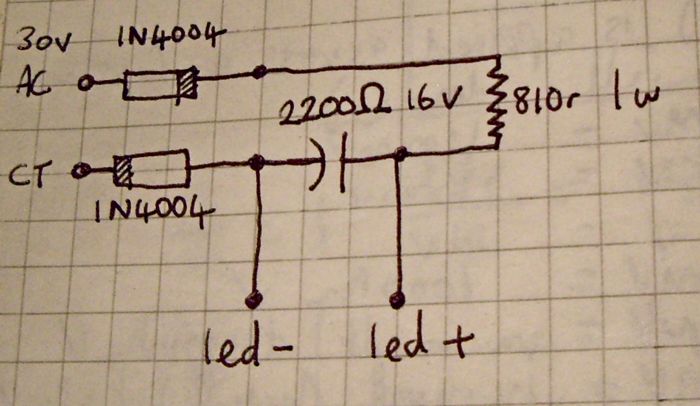
Also I knocked this up to supply the meter LED's, seems to work fine, nothing gets warm but as I'm not an electronics expert I'm slightly concerned I may be doing something stupid - gives 3.9v across the LED's - care to cast your eyes over it?
Ledpowercircuit.jpg

Not sure if i need both diodes? Oops, don't know why i labeled the cap 2200 ohms - should be 2200 uF.


Cheers,

John.
 
On the rev A you need to use tp1? I believe for calibration. NOT r74. That should alleviate your problem. Also set your meter to a couple places. Don't need .00000

Hopefully you soldered a pin up from the test point.

Let me check my notes and will update this post.

John

Edit: think it was TP10 and 11 (test point) And I used a 5k on the rev A from the start. Dunno if I needed it tho. I have 4 rev D's with 2k trimmers.

John
 
As far as my grounding scheme I have one ground wire to each xlr from the case ground next to the IEC connector. and another from there to the board. Dunno if that is correct but have no problems after building 5 of these.

Just an amateur experimenter so others may be able to help you better than I. I made my first one and just stuck with what worked for me.  :)

As far as the LED just use the DC from the board and a quote from gyraf: R=U/I - resistance in Ohms = Voltagedrop (in volts) / current (in Amps) (20 milliamps is .02 amps) hint for most leds.

Ohms law.

John
 
Can anyone verify if R11 (9.1K in preamp) and R31 (3.3K in the line amp) are supposed to be populated?  I've got them on order regardless, but they were missing from the Mouser Cart I used from Hairball's BOM link.  I figured there might be a reason for their omission from the Mouser Cart link in Hairball's specific build?

Thanks!  8)
 
If they're on the board they should be populated.  I need to look at my BOM for the new Rev A in the morning, sounds like it's missing 2 resistors!

Mike
 
Stagefright13 said:
On the rev A you need to use tp1? I believe for calibration. NOT r74. That should alleviate your problem. Also set your meter to a couple places. Don't need .00000

Hopefully you soldered a pin up from the test point.

Let me check my notes and will update this post.

John

Edit: think it was TP10 and 11 (test point) And I used a 5k on the rev A from the start. Dunno if I needed it tho. I have 4 rev D's with 2k trimmers.

John

Bingo! Thanks John, TP 10 & 11 it is. 2k trimmer was fine actually.

I'll tidy up the wiring and post a pic.

John.
 

Latest posts

Back
Top