spase
Well-known member
spase said:can i use toroidal transformers with this spec (2x24V, 50VA) for this project ? Thank you.
anyone ?


spase said:can i use toroidal transformers with this spec (2x24V, 50VA) for this project ? Thank you.
spase said:spase said:can i use toroidal transformers with this spec (2x24V, 50VA) for this project ? Thank you.
anyone ?

atticmike said:I'm rather concerned whether the Dual Primary (115V/230V) Toroidal 2X25 30VA Power Transformer is able to handle two units at the same time without running hot?
atticmike said:Does anyone know why at the wiring pages, a small resistor is attached to the release pot but on the bom, there is nothing?
So no resistor to the release pot or is it missing in the bom?
Mike
atticmike said:Does anyone know why at the wiring pages, a small resistor is attached to the release pot but on the bom, there is nothing?
So no resistor to the release pot or is it missing in the bom?
Mike
Echo North said:atticmike said:Does anyone know why at the wiring pages, a small resistor is attached to the release pot but on the bom, there is nothing?
So no resistor to the release pot or is it missing in the bom?
Mike
MNATS' BOM is always the official BOM. Mine is just there for people who want to use the mouser cart and it is not guaranteed to be accurate (though I think they are). R57 is on my BOM as well.
Biasrocks said:ChrioN said:I can trace through the whole unit with from [after the input transformer] to [before the output transformer] and get excellent results. But as soon as I go through one of the transformers things gets ugly.Biasrocks said:Make yourself a signal tracer and trace the signal and find out where it disappears.
Mark
So it's getting lost in the output transformer.
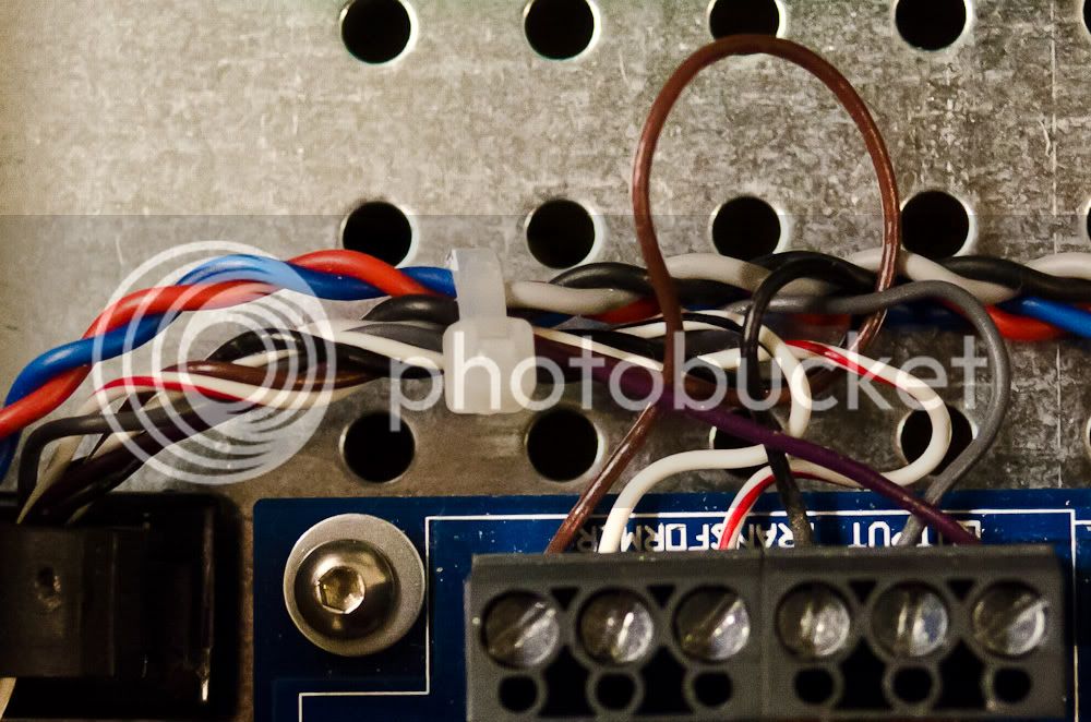
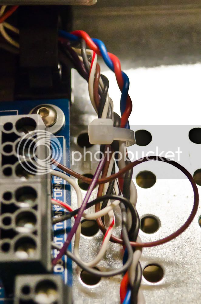
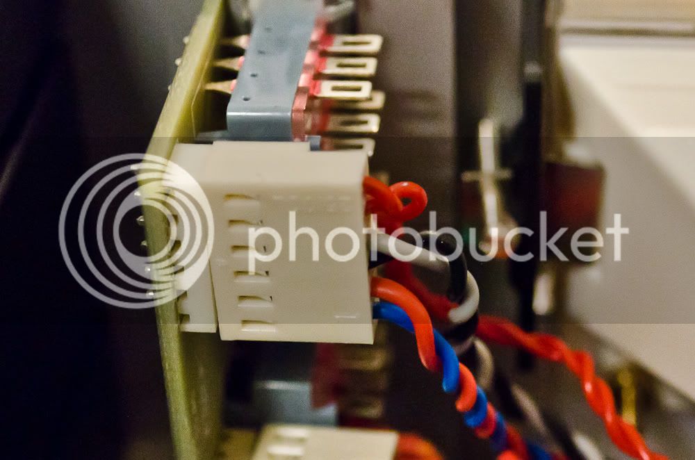
How about a photo of the output transformer wiring from the board to the XLR out.
Mark
ChrioN said:Biasrocks said:ChrioN said:I can trace through the whole unit with from [after the input transformer] to [before the output transformer] and get excellent results. But as soon as I go through one of the transformers things gets ugly.Biasrocks said:Make yourself a signal tracer and trace the signal and find out where it disappears.
Mark
So it's getting lost in the output transformer.
How about a photo of the output transformer wiring from the board to the XLR out.
Mark
Sorry, no photo. But its so straight forward one isn't really needed.
All the colored wires from the hairball output transformer goes to the (of course) correct terminal on the pcb.
Also Yellow and Orange is connected.
Red goes to + on XLR. Blue goes to - on XLR. An extra set of red and blue wires goes from the XLR to the meter PCB as well.
atticmike said:ChrioN said:Biasrocks said:ChrioN said:I can trace through the whole unit with from [after the input transformer] to [before the output transformer] and get excellent results. But as soon as I go through one of the transformers things gets ugly.Biasrocks said:Make yourself a signal tracer and trace the signal and find out where it disappears.
Mark
So it's getting lost in the output transformer.
How about a photo of the output transformer wiring from the board to the XLR out.
Mark
Sorry, no photo. But its so straight forward one isn't really needed.
All the colored wires from the hairball output transformer goes to the (of course) correct terminal on the pcb.
Also Yellow and Orange is connected.
Red goes to + on XLR. Blue goes to - on XLR. An extra set of red and blue wires goes from the XLR to the meter PCB as well.
the whole wiring is easy as long as you mind every step and read everything carefully.
What I'd appreciate some experience on would be the wiring of the power transformer in 230 v countries with the hairballaudio kit's transformer.
Mike
Biasrocks said:ChrioN said:Sorry, no photo. But its so straight forward one isn't really needed.
A photo is worth a thousand words, and I'm not going to pull my blue face out of the rack to see how it's hooked up. Your move.
Am I correct that your getting signal right up to the output transformer?
Regards,
Mark
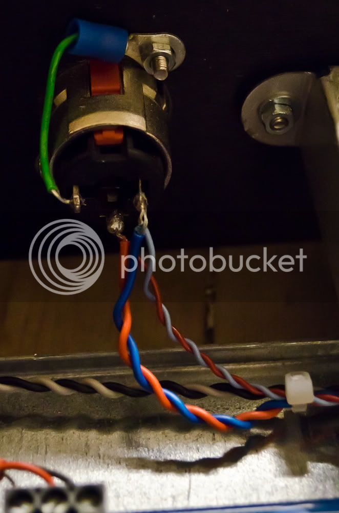


Biasrocks said:Your output XLR is miss wired, you have the ground and pin 2 reversed.
Switch the GREEN and BLUE wires.
Mark
ChrioN said:Those are 1/4" connectors, not XLR. They are wired in a different way. http://www.neutrik.com/zoolu-website/media/document/2802/Drawing+NJ3FP6C


