Well I assume there are some people like me who never get sick of seeing finished projects so here goes...
Disclaimer: Sorry these pics suck...I am the worst photographer on the planet.
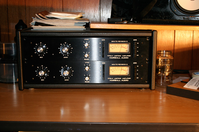
Here are a pair of beauties a built over the holidays.
Front of Both
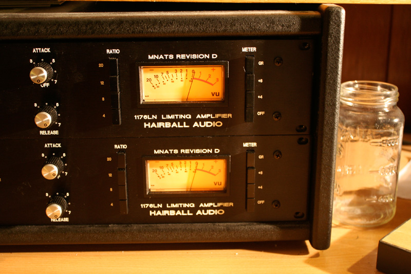
VU and Pushbuttons
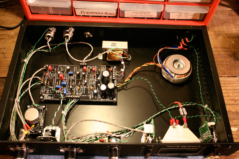
Inside one unit...they both look the same inside
")
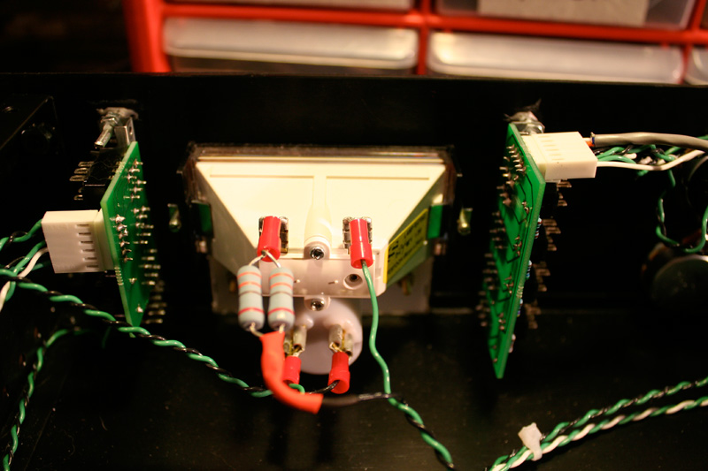
Rear of VU showing pushbutton mounting discussed in other thread
I had a great time...no major issues.
Notes:
- I have RCA connectors on the back for eventual stereo connection. I will deal with this later.
- Put the "0 adjust" multi turn put up near the front panel using a little bracket...adjustable through a hole in the front like the original.
- Mounting the pushbuttons with a set screw and a little J-B Weld seems solid. Very solid.
- GR Disable is on the attack knob like the original.
- Both units are reading a THD+N of 0.036% following the Purple Audio procedure. I believe this to be good.
- One of the unit's ratios are a little high (around 6.5, 12, 15, 30 if I recall). The other unit's ratios are correct. I'll look into this in a bit...too tired right now.
- Used Skylar's input grounding technique...both units are dead quiet.
- I mounted my on board trimmers backwards...which is fine...just have to turn the trimmers in the opposite direction the calibration manuals say...but you haven't built yours yet...go the opposite way I did
I think that's it!
I'm lending them to a local studio for a few weeks to get some feedback. They have a pair of original D's and will give them a good work and provide a better review than I could give.
Thanks Mako and everyone who chips in on the thread!
Mike


![Soldering Iron Kit, 120W LED Digital Advanced Solder Iron Soldering Gun kit, 110V Welding Tools, Smart Temperature Control [356℉-932℉], Extra 5pcs Tips, Auto Sleep, Temp Calibration, Orange](https://m.media-amazon.com/images/I/51sFKu9SdeL._SL500_.jpg)