[BUILD] 1176LN Rev D DIY

GroupDIY Audio Forum

Help Support GroupDIY Audio Forum:

This site may earn a commission from merchant affiliate links, including eBay, Amazon, and others.
As long as you've mounted the trimmer right, it's ok if the 3 holes that are connected flow together.  Only the wiper pin should be in those middle pads (if you're using the ones on the Hairball BOM).

See the build guide on my site for orientation.
 
Thanks Monsieur Echo,

I've just put them in and just about managed to avoid them flowing together,thought I'd just be on the safe side....then realised I've been a dumb dumb and put them in the wrong orientation :eek:....as clearly shown on your page with a nice picture just to make things really clear for idiots with no patience like myself!!

Out comes the pump.....  :-[
 
you must have patience when building gear....the slightest error could cause the whole pcb to not work correctly...after all the money you have spent, I would think you would want to take your time!
 
Hallo

I'm just finishing my first 1176 build, Mnats Rev D board and the full Hairball bundle with a Blackface enclosure, just looks awesome! Soon ready for passing audio through the unit and starting calibration so these are exciting times! :)

However, after reading more about input transformers ( http://www.groupdiy.com/index.php?topic=10611.0 ) I just could not resist buying the UTC O-12, found one on ebay and though it might get me a little closer to the original sound. At the same time I bought a UTC A-20 as well.
Being the audionerd that I am I now want to, of course, have both transformers in the unit. So my idea is to install a switch so i can change the input between the O-12 and A-20. More options = happy audionerd! :)

I've built the unit now with the Altran input transformer ( which I'm sure is just excellent ) and plan on getting the thing up and running first, then make the modification when everything else is working. My question is if someone else has tried anything like this before? Is it as simple as I imagine by just adding a DPDT switch after the T-Pad attenuator? Will the calibration be off when switching to the other input transformer?


Any views on this subject would be most appreciated. I also want to say thanks to Mnats and Hairball Audio for their excellent work.


/Edward.
 
Edward said:
Hallo

I'm just finishing my first 1176 build, Mnats Rev D board and the full Hairball bundle with a Blackface enclosure, just looks awesome! Soon ready for passing audio through the unit and starting calibration so these are exciting times! :)

However, after reading more about input transformers ( http://www.groupdiy.com/index.php?topic=10611.0 ) I just could not resist buying the UTC O-12, found one on ebay and though it might get me a little closer to the original sound. At the same time I bought a UTC A-20 as well.
Being the audionerd that I am I now want to, of course, have both transformers in the unit. So my idea is to install a switch so i can change the input between the O-12 and A-20. More options = happy audionerd! :)

I've built the unit now with the Altran input transformer ( which I'm sure is just excellent ) and plan on getting the thing up and running first, then make the modification when everything else is working. My question is if someone else has tried anything like this before? Is it as simple as I imagine by just adding a DPDT switch after the T-Pad attenuator? Will the calibration be off when switching to the other input transformer?


Any views on this subject would be most appreciated. I also want to say thanks to Mnats and Hairball Audio for their excellent work.


/Edward.

Yes a number of people have built units with transformer switching (usually on the output).  Calibration shouldn't be affected but I would consider using a relay (controlled with a mechanical switch on the panel) for switching.
 
Thank you Echo North. I need to do some learning on relays then, sounds like fun.

I have seen the Mohog units with switchable output transformers among others but never seen one with switchable input transformers. I'm gonna give it a try however.


/E
 
hi everybody :)

Do you think my problem of "no compression" comes from my 2N3708 ?


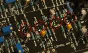
Please take a look as I soldered them :


Is that good ?
Thanks ;)
 
hi,
yesterday I show you my new board. I do an other one. That's why "0" Set was not solder. I reversed the 5457's !!! :)
I replace the board in the comp and that's work => 29,9V and  -9,7V

BUT I GOT THE SAME PROBLEM !!!!
I really dont understand... I will change atack and release pot but I think my comp will NEVER compress I can feel it. pfffffff....

the 3708's are good ???
 
acoustix said:
Have you calibrate your new clone ? (QBias ...)

Is the audio signal passes through it ?

Yes... I did the calibration... exacly the same with the 2 boards. Audio signal is OK and good.... but NO COMPRESSION !
I did an other board for nothing !
 
Hi guys,

I just assembled the first Rev D Blue Stripe with Hairball Kit Compressor but I encountered a problem. Let me describe what we did first:

- the values of the power supply are correct (9,97 V, 29,8 V) -> this is positive
- we double-checked all resistors before we started assembling
- wiring is also correct (double-checked)

Now the big problem:
No signal passes through the compressor and there is only a 50 Hz humming in the output.

In gain reduction view at the VU-meter I can move the needle with the trim pods but in +4 and +8 view the needle does not move at all. All we can hear is the described humming which does not change no matter what setting we've got at the output/input pods.

So, here my question:
What would be the correct values of a 1 kHz tone after the input transformer before it goes to the PCB?
We think the input transformer may be damaged out of the box.
How can I trace the signal on the PCB?


We're really stuck here and feel like noobs! But I think we did a good soldering job. We've also assembled guitar effect boards and they're working just fine.

Please, who can help?!

Greetz from Germany
JazzySeb
 
college101 said:
Did you connect orange and yellow on the output transformer?
Yes, i did... i soldered them together to connect both windings of the transformer.M

I even got no Signal at the VU Meter...
and I think there should be a reading even if the Output Transformer isn`t working properly.
But that's just my guess.

So go Backwards?

I wanted to check if the INPUT Transformer is working right with a 0db, 1kHz tone comming from my DAW.


Jazzyseb said:
college101 said:
Did you connect orange and yellow on the output transformer?
Yes, i did... i soldered them together to connect both windings of the transformer.M

I even got no Signal at the VU Meter...
and I think there should be a reading even if the Output Transformer isn`t working properly.
But that's just my guess.

So go Backwards?

I wanted to check if the INPUT Transformer is working right with a 0db, 1kHz tone comming from my DAW.

For your input, you can "plug" your output's DAW in Unbalanced format directly to the 1176 Input PCB.
But don't put 0dB, in this case you have no T-Pad.

For the output, VU meter is plug directly to the out of the output Transformer, so if out trans don't work, your VU is not working ...

For your Hum, check your ground point and connection between ground PCB and case.
 
Hi again.

first Thx for your reply Acoustix and college101!

Today I did the next round of troubleshooting...
but still no Signal at the Output, no VUreading at +4 and +8... hummig still there...

I've put an unbalanced signal straight to the PCB... no changes :-(


THEN:
I checked my Output transformer against the Specs. from Hairball:

My readings are:
brown->black: 47,6Ohm;
blue->red:48,8Ohm;
grey->violet: 252Ohm
This is when yellow and orange wire are connected
when they are not connected, my reading is:
blue->yellow: 26,6Ohm and
red->orange:22,3Ohm
i guess these are my 2 reading that make 48,8Ohm when the yellow and orange are connected;-)

So in the Hairball Datasheet http://hairballaudio.com/docs/5002/5002.pdf there is 600 Ohm between red and blue; brown and black and grey and violet.
My Measurements are far away from that.
So is my Outputtransformer not right/broken?

Next question: Do the main PCB needs ground connection where it is mounted on the rails?
The Points where the screws are, have no connection to anything! (I think...)
I've check the ground of C25 to case, all case parts to each other, the ground of XLR in/out, of the input transformer, all ground connections on the PCB like the pads next to pad7 and between pad 18 and 22... All are good. but i still get a frustrating humming at the output!

So i even bought a new multimeter witch can measure Frequencies... so can i chase my Signal on the PCB?
If so... Where should i measure?

Any other Suggestions?

Any Idea where to look next?

Help!

Jazzyseb


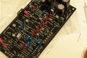
Post some close up pics of your soldering job... My first mistake with my first build was over soldering, which ruined the board..

I got a new board, new parts, re-did the solder job, and presto...worked first try
 

Latest posts

Back
Top